Les, (GDM8085),
Pardon for being late to the party; I just stumbled upon this thread. I too have been doing an lighting package with full retrofit on a 15 GTI SE. Finished installing the last part yesterday. I still have a communication error (12601088 - Databus U1201 00 [137] - No Communications) and not sure if the is working as cornering lights are not working. However, have lights fully operational, is programmed and it has programmed the slave modules. Lights do the shimmy, up and down at start up and module executes basic setting and acknowledge basic settings after adjusting headlights. My communication issue is likely caused as I am connecting to the to CANBUS + and - at pin 9 and 19 respectively as my pins 7 and 17 were missing coming out of the J533 diagnostic buss. I used Diagnostic Can Bus high and low connection 1 rather than the CAN Bus extended high and low connection 1 which is what is used to communicate with module. I am quickly coming to the conclusion that not all CAN bus are the same. Just ordered proper diagnostic buss. Will give me time to step back from this project for a few days to psychologically heal. With your replacement you have had significant more challenges then I. I will post my DIY when I have all the bugs worked out. Below are some excerpts you may be able to use on coding and adaptation changes.
Best,
George
Process Overview:
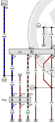
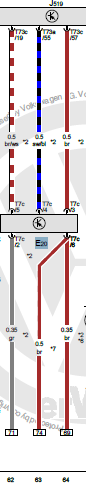
You may want to familiarize yourself with schematic and process.
Run cable from headlights through firewall.
Temporarily install Headlights
Connect xenon shutter wires to .
Make VAGCOM changes and check that lights function. Button up headlights.
Connect to Control module wires to CANBUS, power and ground, and headlight motors. Connect +12V supply to headlights. Securely mount Control Module.
Mount level sensor
Run cable from sensor to control module.
VAGCOM changes to introduce to CANBUS and Code .
Adjust Headlight.
Make VAGCOM changes and check that lights function. Check that the lights work. I had buttoned up everything, and found I had a bad bulb. At this point your basic light should work. You won’t have high beams or DRL without significant VAGCOM changes. You will need to make changes to adaptation setting for light (Leutche) channels 2, 3, (left and right parking light) 4, 5, (left and right DRL) 8, 9, left and right (high beam) 10, and 11 (left and right shutter to control high beam).
Don (DV52) our forum hero who has spent many an hour putting tutorials and information together for the benefit of the community put together a comparison matrix of a number of over twenty MK7 GTI configuration. I took a column that had my car and one that had a lighting package and did a comparison of the light channels 0 through 11 to determine what changes needed to be made. The file is located here:
https://www.dropbox.com/s/me4v48fa8nd9dz3/BCM_Compare_8_6.xlsx?dl=0 Your configuration may be different, but for mine I had to make the following changes: For light channels 2 and 3 adaptation files 1, 2, 3, 4, 8, 11, 12, 13, and 14 needed to be changed. For light channels 4 and 4 adaptation files 1, 2, 3, 6, 13, and 14 needed to be changed. For light channels 8 and 9 adaptation files 1, 2, 3, 4, 5, and 6 needed to be changed. For light channels 10 and 11 adaptation files 1, 2, 3, 4, 5, and 6 needed to be changed. My changes are below.
Code:
Leuchte10SHUTTER LB23-Lasttyp 10 from not active to 2 - Shutter: Diagnosesensierung für 'LED low' Leuchte10SHUTTER LB23-Lampendefektbitposition 10 from 0 to	37
Leuchte10SHUTTER LB23-Lichtfunktion A 10 from not active to Left high beam
Leuchte10SHUTTER LB23-Fehlerort mittleres Byte DTC-DFCC 10	from 0	to 1E
Leuchte10SHUTTER LB23-Lichtfunktion B 10 from not active to Lichthupe generell
Leuchte10SHUTTER LB23-Dimmwert AB 10 from	 0 to 127

Leuchte11SHUTTER RB22-Lasttyp 11 from not active to 2 - Shutter: Diagnosesensierung für 'LED low'
Leuchte11SHUTTER RB22-Lampendefektbitposition 11 from 0 to 41
Leuchte11SHUTTER RB22-Fehlerort mittleres Byte DTC-DFCC 11 from 0	to 1F
Leuchte11SHUTTER RB22-Lichtfunktion A 11 from not active to Right high beam
Leuchte11SHUTTER RB22-Lichtfunktion B 11 from not active to Lichthupe generell
Leuchte11SHUTTER RB22-Dimmwert AB 11 from 0 to 127

Leuchte2SL VLB10-Lasttyp 2 from 10 - allgemeine Scheinwerfer 	to 4 - LED Tagfahrlichtmodul Signal
Leuchte2SL VLB10-Lampendefektbitposition 2 from 0 to 48
Leuchte2SL VLB10-Fehlerort mittleres Byte DTC-DFCC 2 from 45	to 4A
Leuchte2SL VLB10-Lichtfunktion A 2 from Standlicht allgemein (Schlusslicht: Positionslicht: Begrenzungslicht) to Daytime running lights
Leuchte2SL VLB10-Lichtfunktion C 2 from not active to Blinken links aktiv (beide Phasen)
Leuchte2SL VLB10-Dimming Direction CD 2 from	 maximize to	minimize
Leuchte2SL VLB10-Lichtfunktion E 2 from not active to Standlicht allgemein (Schlusslicht: Positionslicht: Begrenzungslicht)
Leuchte2SL VLB10-Lichtfunktion F 2 from not active to Parklicht links (beidseitiges Parklicht aktiviert li & re)
Leuchte2SL VLB10-Dimmwert EF 2 from	0 to 26

Leuchte3SL VRB21-Lasttyp 3 from 10 - allgemeine Scheinwerfer 	to 4 - LED Tagfahrlichtmodul Signal
Leuchte3SL VRB21-Lampendefektbitposition 3 from 0 to 4C
Leuchte3SL VRB21-Fehlerort mittleres Byte DTC-DFCC 3 from 46	to 4C
Leuchte3SL VRB21-Lichtfunktion A 3  from Standlicht allgemein (Schlusslicht: Positionslicht: Begrenzungslicht) to Daytime running lights
Leuchte3SL VRB21-Lichtfunktion C 3  from not active to	Blinken rechts aktiv (beide Phasen)
Leuchte3SL VRB21-Dimming Direction CD 3  from maximize to minimize
Leuchte3SL VRB21-Lichtfunktion E 3  from not active to Standlicht allgemein (Schlusslicht: Positionslicht: Begrenzungslicht)
Lichtfunktion F 3 from not active to Parking light right
Leuchte3SL VRB21-Dimmwert EF 3 from 0 to 26

Leuchte4TFL LB4-Lasttyp 4 from	9 - allgemeine Glühlampe 27W: auch H15 to 1 - LED Tagfahrlichtmodul Versorgung
Leuchte4TFL LB4-Lampendefektbitposition 4 from 48 to	3A
Leuchte4TFL LB4-Fehlerort mittleres Byte DTC-DFCC 4 from 43 to 49
Leuchte4TFL LB4-Dimmwert AB 4 from 100 to 127
Leuchte4TFL LB4-Lichtfunktion F 4 from	not active to Parklicht links (beidseitiges Parklicht aktiviert li & re)
Leuchte4TFL LB4-Dimmwert EF 4 from 31 to 127

Leuchte5 TFL RB32-Lasttyp 5 from 9 - allgemeine Glühlampe 27W: auch H15 to 1 - LED Tagfahrlichtmodul Versorgung
Leuchte5 TFL RB32-Lampendefektbitposition 5 from 4C to 44
Leuchte5 TFL RB32-Fehlerort mittleres Byte DTC-DFCC 5	from 44	to 4B
Leuchte5 TFL RB32-Dimmwert AB 5 from 100 to	127
ENG116555-Leuchte5 TFL RB32-Lichtfunktion F 5 from not active to Parking light right
Leuchte5 TFL RB32-Dimmwert EF 5 from 31 to 127


Leuchte8FL LB39-Lasttyp 8 from	10 - allgemeine Scheinwerfer to	36 - LED Kleinleistung
Leuchte8FL LB39-Lampendefektbitposition 8 from 37 to	35
Leuchte8FL LB39-Fehlerort mittleres Byte DTC-DFCC 8 from 1C to 26
channel ENG116944-ENG116027-Leuchte8FL LB39-Lichtfunktion A 8 from Left high beam to Standlicht allgemein (Schlusslicht: Positionslicht: Begrenzungslicht)
Leuchte8FL LB39-Lichtfunktion B 8 from	Lichthupe generell to Parklicht links (beidseitiges Parklicht aktiviert li & re)
ENG116029-Leuchte8FL LB39-Dimmwert AB 8 from 100	to 127

Leuchte9FL RB2-Lasttyp 9 from 10 - allgemeine Scheinwerfer to 36 - LED Kleinleistung
Leuchte9FL RB2-Lampendefektbitposition 9 from 41 to	3F
Leuchte9FL RB2-Fehlerort mittleres Byte DTC-DFCC 9 from 1D to 27
Leuchte9FL RB2-Lichtfunktion A 9 from Right high beam to Standlicht allgemein (Schlusslicht: Positionslicht: Begrenzungslicht)
Leuchte9FL RB2-Lichtfunktion B 9 from Lichthupe generell to Parking light right
Leuchte9FL RB2-Dimmwert AB 9 from 100 to 127
I also made vagcom coding changes to let car know I have xenon lights, byte 2 bi-xenon without light assist, and byte 6 bit 5-6 xenon shutter installed.
You now have properly functioning lights, but you do not have .
Connect Control module wires to CANBUS, power and ground, headlight motors controller and +12V supply to headlights. Securely mount Control Module – Now the fun.
Let’s find where we are and think about what we are doing next. The module is normally mounted up in the dash next to the diagnostic module. I decided to mount just to the right of the as there is a place to wedge and I could secure with long cable tie. I mention so you can determine wire lengths as you are brining everything together so you can use existing runs to make things nice and neat. Most of the below operations are not order dependent. You can mount module in other places such as footwell as there is room.
The harness coming from the firewall has two sets of twisted pair (going to motor controller) and power. Tie one set of twisted pair into the other with the terminal pins making sure orange/grey and orange/black go to the same. Install the orange/grey wire to pin 4 and orange/brown wire to pin 5 of connector.
Finding the CANBUS wires going into the module is no joy. It is not in the TIUL (connector by footwell), where they would be if LP was installed. On schematic, it is pins 7 and 17 of Diagnostic module, buried way up in dash; however, when you access there are no pins 7 and 17 coming out of diagnostic module. I tapped into CANBUS Diagnostic pins 9 (low) and 19 (high), by tapping into wires coming from 9 (orange/brown) and 19 (orange/red). You can do the same or look at wiring harness and see if you can find a CANBUS pair of wires, they will be a twisted pair orange/brown and orange/black. Install CANBUS + to pin 2 and CANBUS – to pin 3.
NOTE: I still have a communication problem, but above is what I did.
VAGCOM changes to introduce to CANBUS, Code - Use Vagcom to tell CANBUS module that control module has been added. Select 19 CAN Gateway, then installation list and check the box next to 55 Xenon Range and execute. Note when the is properly coded it will automatically code the slave modules on the lights. I attempted to use the long coding and check what was applicable; however, received errors. Finally used admap from Rosstech forum for 2016 GTI Autobahn: Coding: 021A01010B000400 Changed the bit from to so ended up with 021A01000B000400.
Code:
Address 55: Headlight Range (J745)       Labels: 7P6-907-357.clb
   Part No SW: 7P6 907 357 A    HW: 7P6 907 357 A
   Component: AFS-ECU       H07 0080
   Revision: --------    Serial number: --------------
   Coding: 021A01000B000400
   Shop #: WSC 01608 666 28888
   ASAM Dataset: EV_HeadlRegulVWAFSMQB 001120
   ROD: EV_HeadlRegulVWAFSMQB.rod
   VCID: 3D5FCAA7ACB8CCA9C8-8068

   Left Headlamp Power Output Stage:
   Subsystem 1 - Part No SW: 5N0 941 329     HW: 5N0 941 329   Labels: 3D0-941-329.CLB
   Component: LeiMo links  H01 0004
   Coding: 2E0000

   Right Headlamp Power Output Stage:
   Subsystem 2 - Part No SW: 5N0 941 329     HW: 5N0 941 329   Labels: 3D0-941-329.CLB
   Component: LeiMo rechts  H01 0004
   Coding: 2E0000

3 Faults Found:
12601088 - Databus
          U1201 00 [137] - No Communications
          MIL ON - Confirmed - Tested Since Memory Clear
             Freeze Frame:
                    Fault Status: 00000001
                    Fault Priority: 6
                    Fault Frequency: 6
                    Reset counter: 107

13705474 - Databus
          U1121 00 [137] - Missing Message
          MIL ON - Confirmed - Tested Since Memory Clear
             Freeze Frame:
                    Fault Status: 00000001
                    Fault Priority: 2
                    Fault Frequency: 1
                    Reset counter: 107

13705481 - Databus
          U1121 00 [137] - Missing Message
          MIL ON - Confirmed - Tested Since Memory Clear
             Freeze Frame:
                    Fault Status: 00000001
                    Fault Priority: 6
                    Fault Frequency: 1
                    Reset counter: 107