Im new here. Jack, don't cut me deep. but please help.

Status
Not open for further replies.
   #61  

Catahula

On Probation
Joined
Jun 11, 2018
Messages
52
Reaction score
17
Location
Woodinville, WA.
VCDS Serial number
C?ID=33412
With this ER-Win dilley-oh, I'm guessing I can pay for a day and either screen shot or print to PDF?

If so, it sounds like a good deal and a great tool.

unfortunately, I need to go to work for the rest of the week, so I won't be able to get everything I need until Saturday.
 
   #63  

Catahula

On Probation
Joined
Jun 11, 2018
Messages
52
Reaction score
17
Location
Woodinville, WA.
VCDS Serial number
C?ID=33412
403738 -5/-5 Inverse/Televerse Intern/Extern!

OK. I give. What is this mathematical mess?

Compression came back at 178-180 across the board, I haven't had time to check the O2 sensors, or the heating elements.

would the heating elements cause the fuel pump to not get power?

This still seems like IMMO stuff that I don't have on my car (unless APR loads it when they flash).

If so, how do I reset to get my car running again to check the stoopid misfire thing?
 
Last edited by a moderator:
   #64  

Jack@European_Parts

Gone But Not Forgotten
Professional VCDS User
Joined
Jan 29, 2014
Messages
21,923
Reaction score
9,308
Location
Montgomery, NY, USA
VCDS Serial number
C?ID=57337
Doesn't sound like immo to me...
What's the status Kahlua?

New scan and consider stock controller with more consistent diagnostic stack.
 
   #65  

Catahula

On Probation
Joined
Jun 11, 2018
Messages
52
Reaction score
17
Location
Woodinville, WA.
VCDS Serial number
C?ID=33412
10-4


403738 -5/-5 Inverse/Televerse Intern/Extern!

Nop Nop Nop.............give me a little EAX!

WHAT IS THIS MATHEMATICAL MESS?!?

Hi Jack.

I was starting to wonder if I broke you.

I'm working on the ER-WIN download. I still have no start, just crank
I probed a bunch of sensors to create a list of things to compare to the manual.
 
   #66  

Jack@European_Parts

Gone But Not Forgotten
Professional VCDS User
Joined
Jan 29, 2014
Messages
21,923
Reaction score
9,308
Location
Montgomery, NY, USA
VCDS Serial number
C?ID=57337
It is Pop Secret Magic Clearance only.

https://goo.gl/images/iP8FeM

Check consumers for short on bus and all fuses
Especially deleted OXS sensor heaters.

You didn't break me Kahlua, others are just wearing me thin and down.
I am off world in the land of broken toys.
 
   #67  

Catahula

On Probation
Joined
Jun 11, 2018
Messages
52
Reaction score
17
Location
Woodinville, WA.
VCDS Serial number
C?ID=33412
I got the car to start.

The owner's manual and the cap for the fuse box don't match at all. The fuse that was blown was listed as "rear wiper". I personally don't have one of those on my sedan. The manual showed the correct layout, and shazam. It started.

I still have a small (now its smaller) missfire around 3500.

-new N75
-new Crankshaft position sensor
-new EGT's
-new ground for the coils.....which brings me to my next question....

How about those pictures to make my coils all Jackcellent?
 
   #68  

Jack@European_Parts

Gone But Not Forgotten
Professional VCDS User
Joined
Jan 29, 2014
Messages
21,923
Reaction score
9,308
Location
Montgomery, NY, USA
VCDS Serial number
C?ID=57337
How about those pictures to make my coils all Jackcellent?

All in good time.......been busy with new PC stuff, speed and security upgrades.

What fuse and why did it blow and what is on the track?
 
   #69  

Catahula

On Probation
Joined
Jun 11, 2018
Messages
52
Reaction score
17
Location
Woodinville, WA.
VCDS Serial number
C?ID=33412
Fuel pump, which has just about everything important to run on it.
-MAF
-O2 sensors
-N80 EVAP
Probably more than that running through the fuse, at least some of the legs for relays.

I also found a couple of ignition fuses blown. My shrink wrap went south on me.
 
   #70  

Jack@European_Parts

Gone But Not Forgotten
Professional VCDS User
Joined
Jan 29, 2014
Messages
21,923
Reaction score
9,308
Location
Montgomery, NY, USA
VCDS Serial number
C?ID=57337
Inadequate grounds will indeed do that but so will SPORADIC OXS sensors!
 
   #71  

Catahula

On Probation
Joined
Jun 11, 2018
Messages
52
Reaction score
17
Location
Woodinville, WA.
VCDS Serial number
C?ID=33412
Ok. I got this on my tester.
Code:
                             Pos.4                             Pos. 2                        Pos.2                    Pos.1
    Green# 609        .3v                                 0 ohms                       3.4v                     1.6v
    Brown# 610        .3v                                 0 ohms                       3.4v                     1.6v
    Black Pass rear    .3v                                 0 ohms                       2.1v                     1.6v
    Black Drivers rear .3v                                0 ohms                       2.1v                      1.6v


Now that I've fixed the fuses, I'm willing to bet that pos. 1 will be Batt voltage.

I'll do some logging on heaters tomorrow to see if they are screwed or what.

Since there are no pictures about this whole coil thing, do you run new triggers to the ecu? From your post with no pictures, what do you mean by running 2 wires to make it a wasted spark? as far as I can tell, that is already a thing on the 2.7. Just to clear up emissions. Unless that is for the 1.8t?
 
   #72  

Jack@European_Parts

Gone But Not Forgotten
Professional VCDS User
Joined
Jan 29, 2014
Messages
21,923
Reaction score
9,308
Location
Montgomery, NY, USA
VCDS Serial number
C?ID=57337
Since there are no pictures about this whole coil thing, do you run new triggers to the ecu? From your post with no pictures, what do you mean by running 2 wires to make it a wasted spark? as far as I can tell, that is already a thing on the 2.7. Just to clear up emissions. Unless that is for the 1.8t?


Kahlua,

What is really so hard about understanding how taking the two wires per coil that are the grounds, further using WD and making them go direct to a bus or directly to battery ground with larger wire to enhance the connectivity or attenuation under load?

If you can't envision this idea for all wires, you should not be working on cars.

I'm not going to re-explain it if you don't get it now.......RTFB these links below!

http://www.flukenetworks.com/knowle...on-insertion-loss-measurement-and-testing-dtx


[h=1]Attenuation (Insertion Loss) Measurement and Testing - DTX CableAnalyzer[/h]
Standards now use the term "insertion loss" and not attenuation.

Electrical signals transmitted by a link lose some of their energy as they travel along the link. Insertion loss measures the amount of energy that is lost as the signal arrives at the receiving end of the cabling link. The insertion loss measurement quantifies the effect of the resistance the cabling link offers to the transmission of the electrical signals.
image001_25.gif


Insertion loss characteristics of a link change with the frequency of the signal to be transmitted; e.g. higher frequency signals experience much more resistance. Stated a different way, the links show more insertion loss for higher frequency signals. Insertion loss is therefore to be measured over the applicable frequency range. If you test the insertion loss of a Category 5e channel, for instance, the insertion loss needs to be verified for signals ranging from 1 MHz to 100 MHz. For Category 8 links the frequency range is 1 through 2000 MHz. Insertion loss also increases fairly linearly with the length of the link. In other words, if link "A" is twice as long as link "B", and all other characteristics are the same, the insertion loss of link "A" will turn out twice as high as the insertion loss of link "B."
image002_20.gif


Insertion loss is expressed in decibels or dB. The decibel is a logarithmic expression of the ratio of output voltage (voltage of the signal received at the end of the link) divided by input voltage (the voltage launched into the cable by the transmitter).

Results Interpretation
The insertion loss in a cable is largely dependent upon the gauge of wire used in constructing the pairs. 24 gauge wires will have less insertion loss than the same length 26 gauge (thinner) wires. Also, stranded cabling will have 20-50% more insertion loss than solid copper conductors. Field test equipment will report the worst value of insertion loss and margin, where the margin is the difference between the measured insertion loss and the maximum insertion loss permitted by the standard selected. Hence a margin of 4 dB is better than 1 dB.

Troubleshooting Recommendations
Excessive length is the most common reason for failing insertion loss. Fixing links that have failed insertion loss normally involves reducing the length of the cabling by removing any slack in the cable run.

Excessive insertion loss can also be caused by poorly terminated connectors / plugs. A poor connection can add significant insertion loss. Your clue to this cause is to compare the insertion loss on the four pairs. If only one or two pairs have high insertion loss, this suggests an installation issue. If all pairs have too much insertion loss, check for excess length. However, impurities in the copper cable can also cause insertion loss failures; again this typically happens on one pair only.
Prolonged exposure to water or excessive use of water-based cable lubricants can also increase Insertion Loss and degrade cabling performance. If cables are allowed to dry for a sufficient amount of time after excessive exposure to water, the Insertion Loss performance will typically return to normal. To avoid problems, ensure water isn’t allowed to become trapped in conduits and follow manufacturers’ instructions for the correct amount of cable lubricant to be used.

Temperature also affects insertion loss in some cables. The dielectric materials, which form the conductor insulation and cable jacket, absorb some of the transmitted signal as it propagates along the wire. This is especially true of cables containing PVC. PVC material contains a chlorine atom which is electrically active and forms dipoles in the insulating materials. These dipoles oscillate in response to the electromagnetic fields surrounding the wires, and the more they vibrate, the more energy is lost from the signal. Temperature increases exacerbate the problem, making it easier for the dipoles to vibrate within the insulation. This results in increasing loss with temperature.

For this reason, standards bodies tend to specify insertion loss requirements adjusted for 20C. Cables operating in temperature extremes can be subject to additional insertion loss and where this is likely, the design of the cabling system should take this into consideration. You may not be able to run the maximum 90 meters (295 ft) defined in the standards. Most consultants try and keep runs below 80 meters (262 ft) to provide a safety margin. This of course is not always possible when space is a premium and the number of telecommunications rooms has to be kept to a minimum. From ANSI/TIA-568-C.2 Annex G:

Table1_2.gif


https://solutions.borderstates.com/resource/copper-wire-limitations/
[h=1]Copper Wire Limitations[/h]
[h=1][/h]


Due to the electrical properties of copper wiring, data signals
will undergo some corruption during their travels.
Signal
corruption within certain limits is acceptable, but if the electrical
properties of the cable will cause serious distortion of the signal, that
cable must be replaced or repaired.
As a signal propagates down a length of cable, it loses some of its
energy.
So, a signal that starts out with a certain input voltage,
will arrive at the load with a reduced voltage level. The amount of signal
loss is known as attenuation, which is measured in decibels, or dB. If the
voltage drops too much, the signal may no longer be useful.
Attenuation has a direct relationship with frequency and cable
length.
The high frequency used by the network, the greater the
attenuation. Also, the longer the cable, the more energy a signal loses by
the time it reaches the load.
A signal losses energy during its travel because of electrical
properties at work in the cable.
For example, every conductor
offers some dc resistance to a current (sometimes called copper losses).
The longer the cable, the more resistance it offers.
Resistance reduces the amount of signal passing through the wires –
it does not alter the signal.
Reactance, inductive or capacitive,
distorts the signal.
The two concerns of signal transmission are:

  1. That enough signal gets through. (Quantity)
  2. That the signal is not distorted. (Quality)


http://www.fluke.com/fluke/uses/com...articlecategories/electrical/diagnosevoltdrop

Electrical Automotive Troubleshooting
Diagnosing Voltage Drop
spacer.gif
One of the most rampant electrical maladies showing up in automotive service bays today is the phenomenon known as voltage drop. Left unchecked, voltage drop causes countless unsolved electrical mysteries, especially when it infects the ground side of a circuit. It can also trick you into replacing parts that are not bad.
The more connections and wiring a vehicle has, the more vulnerable the electrical system is to voltage drop.
To contain electrical voltage drop, practice safe electrical service. This means measuring voltage drop before reaching any conclusions. "Voltage dropping" a circuit tell you when the circuit is too restricted to operate a component (motor, relay, light bulb, etc.) or operate it correctly. If the circuit is restricted, repair it and retest. If there is no restriction and the component still does not run or run correctly, then replace the component.
figure1_300p.jpg

In this example, if the water pipe completely collapses, water stops flowing, pressure drops to zero and the water wheel stops turning. Electrically, the same thing happens when a wire falls off or a connection breaks. Current stops flowing, voltage drops to zero. A starter motor would quit or a headlight would go out.
Symptoms of voltage drop
Often confusing and contradictory, electrical voltage drop symptoms vary according to the circuit's job and the severity of the voltage drop.


  • inoperative electrical parts
  • sluggish, lazy electrical devices
  • erratic, intermittent devices
  • devices that work sluggishly or erratically during periods of high electrical loads
  • excessive radio interference or noises in the radio
  • damaged throttle or transmission cables or linkage
  • repeated throttle or transmission cable failures
  • damaged drivetrain parts
  • engine or transmission performance complaints
  • no-starts or hard starts
  • high sensor or computer voltages
  • erratic engine or transmission computer performance
  • false trouble codes in the memory of any on-board computer
  • premature or repeated A/C compressor clutch failure.
This symptom list brings up several points.

  1. Visual inspections miss most cases of electrical voltage drop. You usually can't see the corrosion inside a connection or the damaged wire that is causing the problem.
  2. Ground-side voltage drop, a commonly overlooked cause of electrical trouble, can cause most of these symptoms. Any circuit or component is only as good as its ground.
  3. The more sophisticated electrical systems become, the more important their grounds are. The number of electrical components has increased rapidly and most do not have separate ground wires. Instead, these devices are grounded to the engine or body. Rust, grease, vibration and/or careless repairs often restrict the circuit from the engine/body back to the battery.
  4. Many components such as engine sensors share a common ground. Therefore, a bad ground complicates diagnosis because it affects several components at once.
  5. Some shop manuals and diagnostic charts or fault trees recommend checking grounds last. In reality, it is much quicker to check ground circuits before you climb that fault tree.
  6. It's quicker and smarter to routinely check a circuit's voltage drop than it is to memorize long lists of symptoms. If experience has taught us nothing else, it's that chasing symptoms is no substitute for routine and thorough voltage drop testing.
Experience has taught us other reasons to check voltage drop first. Voltage drop, usually on the ground side, causes inaccurate or bizarre voltmeter readings and oscilloscope patterns. Moreover, when you connect a voltmeter or scope to a system with bad grounds, the test equipment itself can create a good substitute ground. This can be frustrating: as long as your equipment is connected, the circuit works and you can't find anything wrong!
Basic procedures
Whenever an electrical problem gives you fits, take a deep breath and think of the basic electrical building block, the series circuit. Drawings 1 through 7 show basic series circuits. No matter how complicated a system is you can always simplify it into mini-series circuits. Then, inspect each circuit for voltage drop.

Also, relate electricity to water flowing through a water circuit. Water pressure inside the reservoir pushes gallons of water through the pipe. The water turns the water wheel and then flows back into the reservoir. In an electrical circuit, electrical pressure (voltage or volts) pushes electrical volume (current or amps) through the circuit, operating a load. The load may be a computer, a motor, a lamp, a relay, or other device. In the water circuit, the water uses up most of its energy turning the water wheel. Water continues flowing toward the reservoir, but it flows at a lower pressure.
Likewise, electrical pressure (voltage) is used up operating the load. Therefore, voltage falls to about zero on the ground side, but current keeps flowing toward the battery. Because the voltage in a healthy ground circuit should be about zero, some technicians call it ground zero.
figure2_300p.jpg

A kinked return pipe restricts water flow back to the reservoir, slowing down the water wheel and causing a pressure reading on the return side of the wheel. Likewise, ground side voltage drop hurts load performance and causes a voltage reading at the ground side of the load.

Resistance—Restriction
When you think of excessive resistance, imagine a dent or kink that is restricting water flow through a pipe. Common sense should tell you that a kink anywhere in the water circuit (supply side or return side) restricts water flow, causing the water wheel to slow down or stop turning.
Excessive resistance has the same effect on an electrical circuit. Bad connections and broken or under size wires act like a pipe with a kink, restricting current flow. Like the water circuit, restricting current flow anywhere — hot side or ground side — hurts the performance of the load. The effect on the load is hard to predict because it varies with the severity of the restriction. For example, the motor in a restricted circuit may stop working or just run slower than normal.
A restricted circuit can cause an A/C compressor clutch to slip and prematurely burn out. A computer on a restricted circuit may shut off or else work erratically. When corrosion, loose connections or other types of resistance restrict a circuit, volts and amps both drop. If volts drop, amps drop too. That is why when you find a voltage drop in a connection or cable, you know the connection or cable is restricted.

Look at the water circuits in our drawings and remember two critical points. First, a free-flowing ground side is as important as a free-flowing hot side. Second, a ground side restriction is the only thing that causes voltage readings greater than 0–0.1V in any ground circuit.
figure3_300p.jpg

A completely collapsed return pipe stops water flow, stalling the water wheel and causing a system pressure reading at the return side of the wheel. Likewise, a broken ground wire totally blocks current flow, shuts off the load and causes the ground side of the load to read system voltage.

Voltage drop tests
Electrical voltage drop varies according to current flow. Unless you operate the circuit so current flows through it, you can't measure voltage drop. Because an ohmmeter's battery can't supply the current that normally flows through most circuits, ohmmeter tests usually can't detect restrictions as accurately as a voltage drop test.

Open-circuit problems such as broken or disconnected wires or connections stop current flow. After you fix an open circuit, switch the circuit on again and check for lingering voltage drop. Until you get current flowing and check the circuit again, you can't know if the entire circuit is healthy.
Although resistance-free connections, wires and cables would be ideal, most of them will contain at least some voltage drop. If your manuals do not list voltage drop values, use the following as maximum limits:

  • 0.00V across a connection
  • 0.20V across a wire or cable
  • 0.30V across a switch
  • 0.10V at a ground
Because most computer circuits operate way down in the milliamp range, they don't tolerate voltage drop as well as other circuits do. Note that a milliamp is one-thousandth (0.001) amp. The recommended working limit is 0.10V-drop across low-current wires and switches. Testing low-current circuits also requires a high-impedance (10-megohm) voltmeter. A low-impedance voltmeter may load a low-current circuit so much that it gives an incorrect reading or no reading whatsoever! Most professional-grade digital multimeters (DMMs) have 10-megohm input impedance. Using a DMM is the fastest way to accurately measure voltage drops. If the DMM you own does not have autoranging capability, use a low-voltage (0-1 V) scale for voltage drop testing. Remember that test lights are not accurate enough to diagnose electrical voltage drop.Quick ground tests
Because ground circuit voltage drop can cause most of the symptoms listed earlier, consider adopting this new work habit: test grounds first! Before you do a tune-up, check out electrical problems, or test a starting, charging, ABS or air conditioning system, routinely test the engine and body grounds. Connect your DMM between the engine and negative battery terminal. Safely disarm the ignition and crank the engine for a few seconds.

If the voltage drop is excessive, repair the engine ground circuit and retest. Note that on some distributorless ignition systems, the simplest way to prevent the engine from starting during the ground test is to pull the fuel pump fuse. Next, connect the DMM between the negative battery terminal and the vehicle's firewall. Then start the engine and switch on all the major electrical accessories. Too much voltage drop? Then fix the body ground and retest.
Once engine and body grounds are within limits, proceed with your diagnosis. Do not be surprised if fixing these grounds solves the car's problems. The fact that a vehicle passes the body ground test does not mean you can safely ground your voltmeter wherever you want. Some technicians have run themselves in circles for hours because their voltmeters were not well grounded. For safe electrical service, make yourself a 20- or 30- foot jumper wire with an alligator clip on each end. When you have to test an electric fuel pump, lighting system or ABS computer in the rear of the vehicle, ground your DMM to the battery with the jumper wire.
Computer ground kinks
Because computer circuits operate on such low current, the standard ground tests may not reveal a marginal ground on an on-board computer. Before you condemn any on-board computer, check its grounds first. Operate the computer system and backprobe each computer ground terminal. If you measure anything greater than 0.10V, trace that ground circuit and locate the problem.

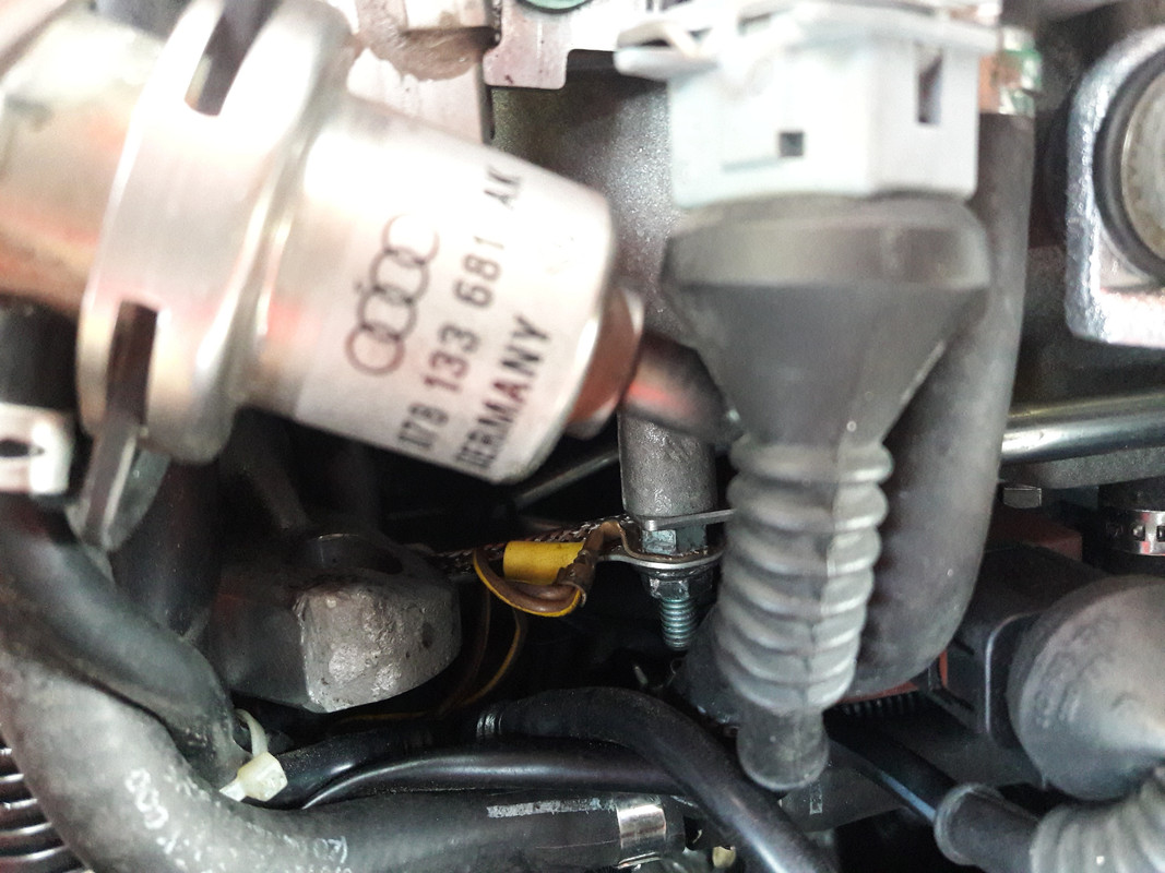
Sometimes, computer grounds are connected to a spot where they are easily disturbed or prone to corrosion, such as a thermostat-housing bolt. Computer connector terminals also can corrode. Removing the connector and spraying the terminals with electrical cleaner may be all it takes to eliminate the voltage drop.
Experience shows that as little as 0.30V on a computer ground terminal can cause trouble. Try pinpointing that with a test light! Poor computer and/or sensor grounds can cause higher-than-normal sensor voltages and false trouble codes. In many cases, the bad ground prevents the computer or sensor from pulling a voltage signal down to or near ground zero. Sure, accessing the computer to check grounds may be a hassle. Nevertheless, mistakenly replacing expensive sensors and computers is a bigger hassle.
figure4_300p.jpg

Connect a DMM across part of a circuit and it directly reads the voltage drop across that wire, cable, switch, or connection. Here, one DMM would display the voltage loss between the battery and the load. The other would show the voltage loss from the ground side of the load to the battery.

Body ground gremlins
Keep your eyes peeled for missing body grounds. If someone else worked on the vehicle, he may have forgotten to reconnect body ground wires or cables. Remember that when the body ground is restricted, current tries to find another route back to the battery. The easiest alternate route may he through the transmission shift cable or the throttle cable. Not only can this current weld the cable together, it also can pit or erode bushings and bearings inside the transmission.

If you find the insulation on the body ground wire is burnt or blistered, you can bet that starter current overheated the wire. When the engine ground is restricted, starter current tries to return to the battery through the body ground circuit. Experience shows that if the body ground circuit can handle the current load, the customer may not notice the problem right away.
Under periods of heavy current flow, a restricted body ground may hamper or shut off a component. For example, turn signals have been known to stop blinking when the driver steps on the brake pedal. Testing confirmed that a restricted body ground choked off the turn signals. The ground could not handle current from the turn signals and brake lights at the same time.
Safe service
Practicing safe electrical service helps you solve electrical problems quicker and more profitably than guessing and swapping parts. Put your DMM to work wiping out electrical voltage drop today. It is the responsible thing to do.

 
Last edited:
   #73  

Catahula

On Probation
Joined
Jun 11, 2018
Messages
52
Reaction score
17
Location
Woodinville, WA.
VCDS Serial number
C?ID=33412
OK. First off...

I got the grounds.. that has nothing to do with what I asked.


If you can't read, then you have no business posting to online forums.


Second, Thanks for posting some useful information for my reading enjoyment!!
 
   #74  

Jack@European_Parts

Gone But Not Forgotten
Professional VCDS User
Joined
Jan 29, 2014
Messages
21,923
Reaction score
9,308
Location
Montgomery, NY, USA
VCDS Serial number
C?ID=57337
OK. First off...

I got the grounds.. that has nothing to do with what I asked.


If you can't read, then you have no business posting to online forums.


Second, Thanks for posting some useful information for my reading enjoyment!!


No Kahlua this is not acceptable..........NOT SORTED!


Since there are no pictures about this whole coil thing, do you run new triggers to the ecu? From your post with no pictures, what do you mean by running 2 wires to make it a wasted spark? as far as I can tell, that is already a thing on the 2.7. Just to clear up emissions. Unless that is for the 1.8t?


No Kahlua


Not a step, an experiment!

Please tell.........
You are not ready to play junk yard wars yet, nor qualified since here with this simple unresolved or aforementioned problems contained in your thread.
http://forums.ross-tech.com/showthr...-Wiring-Upgrades&p=70704&viewfull=1#post70704
 
Last edited:
   #75  

Catahula

On Probation
Joined
Jun 11, 2018
Messages
52
Reaction score
17
Location
Woodinville, WA.
VCDS Serial number
C?ID=33412
Congratulations! You posted a picture of what my grounds looked like a week and a half ago!

I told you I sipped your Kool-aid and made the grounds better.

I'm asking a question from the post YOU DIRECTED ME TOO.

"Step 5. Run new trigger leads back to ecu for each coil, & with larger diameter wire to improve the signal.....further it should be shielded!

Running the wires as a twisted pair will suffice.........

Note : I have experimented with making a two wire bus from the ecu by splitting off ZYL's 1-4 and 2-3........ than by pairing them.
This nets a waste spark principle, and allows for plug cleaning, additionally as an anti foul method for rich race mixtures.
Further this was found to improve emissions, by lowering CAT amplitude efficiency threshold, & because of a more completed burn on stock cars!"

Don't act like I'm trying to do anything but ask a question. Don't tell me what I'm qualified to do. I CAN read.
How many times did you screw things up before you got it all right? Huh, Jack?

Really? I thought we got past you belittling me.
 
   #76  

Jack@European_Parts

Gone But Not Forgotten
Professional VCDS User
Joined
Jan 29, 2014
Messages
21,923
Reaction score
9,308
Location
Montgomery, NY, USA
VCDS Serial number
C?ID=57337
Don't act like I'm trying to do anything but ask a question. Don't tell me what I'm qualified to do. I CAN read.

I do it out of inverse hate to protect you, not belittle you & because it pisses you off enough to wake you up to think....

How many times did you screw things up before you got it all right? Huh, Jack?
Oh I am sure I'm screwing something up and probably don't know what it might be right now.......who fuckin knows! ;)

Really? I thought we got past you belittling me.

The title of your thread you should expect it, and FYI : I only break my friends balls, if I am quiet you better watch out!

Come on man what is so "hard" about twisted pairs for shield?

Again the larger dick wire method for your cars pleasure?

https://en.wikipedia.org/wiki/Shielded_cable

https://en.wikipedia.org/wiki/Twisted_pair
 
   #77  

Catahula

On Probation
Joined
Jun 11, 2018
Messages
52
Reaction score
17
Location
Woodinville, WA.
VCDS Serial number
C?ID=33412
You still haven't answered the question.

read again.

try hard. I used some words. words with a question mark at the end.

Do I need to lead you back to it?


do you run new triggers to the ecu? From your post with no pictures, what do you mean by running 2 wires to make it a wasted spark? as far as I can tell, that is already a thing on the 2.7. Just to clear up emissions. Unless that is for the 1.8t?

I didn't ask about twisted, shielded, grounds, or for some Pop Secret bullshit.

That's a fact, Jack.

1/hate is still hate.

that's an inverse.
 
Last edited:
   #78  

Jack@European_Parts

Gone But Not Forgotten
Professional VCDS User
Joined
Jan 29, 2014
Messages
21,923
Reaction score
9,308
Location
Montgomery, NY, USA
VCDS Serial number
C?ID=57337
Just setup the stock config and use the Hitachi coils with larger grounds and new leads to triggers from ECU and enhanced power wire bus too.
Don't worry about waste spark technics's for ME 7.1/7.1.1 or the shields until the miss is fixed.
Put car back to stock.
 
   #79  

Catahula

On Probation
Joined
Jun 11, 2018
Messages
52
Reaction score
17
Location
Woodinville, WA.
VCDS Serial number
C?ID=33412
Wow.

My question STILL isn't answered.

I'm STILL NOT TRYING TO CHANGE ANYTHING TO WASTED SPARK......

I'M ASKING A VERY SPECIFIC QUESTION.

Your answer is "unaccaptable" "Bullshit" "Horse shit" and some other choice quotes coming straight from you.

This is on the list of "Catahula's List Of Unanswered Questions" CLOUQ if you will.

see what i did there?
 
Status
Not open for further replies.
Back
Top