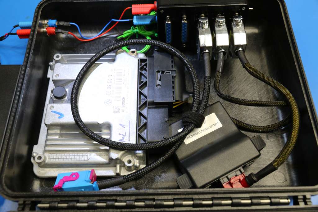
Testbench setup?

   #101  

DV52

Verified VCDS User
Verified
Joined
May 16, 2014
Messages
5,469
Reaction score
5,935
Location
Melbourne, Australia
VCDS Serial number
C?ID=194404
I do need it! :thumbs: I'm merely interested in a permanent terminal 15 solution so other modules can power up and talk to VCDS.

Eric: Here you go_

VgaDXNR.png


I'm not sure if you "Yanks" get taught these diagrams the same as us Southerners, but I hope the table is self explanatory

I've shown the way the Key-switch connector locks into the body of the steering module in the lower LHS to indicate the relative position of pin#1

Lastly, I suspect that you probably know having hooked-up the steering module to your test-bench, but the PC board into which the key-switch connector fits is double-sided. So the Pins make contact on both sides of the board as shown in the lower LHS picture

Don
 
Last edited:
   #102  

SI-R32

Verified VCDS User
Verified
Joined
Apr 30, 2014
Messages
16
Reaction score
12
Location
UK
VCDS Serial number
C?ID=99715
I have a little set up like this for use on BT, RNS, gateway and window modules. i'm having a small issue that I can't get round hoping someone can help.

so with regard to the window wiring i'm mainly connecting gen 3 units so + power on 20 and 18, - on 19, can on 8 and 9, so I wanted to talk to a gen 2 unit the other day the only difference being pin 18 is now pin 12 for gen 2, but for the life of me it will not connect to the unit, elsa tell me can connections are the same going to convenience pins on the gateway. power all tested and all ok, one gen 2 unit is vw the other two are seat, so I even changed the vehicle manufacturer between vw and seat in the gateway but still won't talk to the modules.

any idea please.

thanks
 
   #103  

Eric

Active Member
Staff member
Ross-Tech Employee
Joined
Jan 29, 2014
Messages
3,904
Reaction score
5,799
Location
Lansdale, PA, USA
VCDS Serial number
HC800000
Eric: Here you go_

VgaDXNR.png

Victory! Your table matches perfectly the old MQB diagram we found after I came begging for your assistance:
qHk91xh.png

however I hadn't bothered connecting pins T16r/7-14-16 to their mates on 09, because, who needs that, right? :) Seriously, why can't 16 determine the switch status on its own!?
Anyway, now the measuring values show terminal 15 going to ON when I short 3-5-6. Thanks Don, you gave me the determination to look further than just the switch connection, once I knew we had it right :thumbs:
Bonus video produced and directed by Andy:
 
   #105  

DV52

Verified VCDS User
Verified
Joined
May 16, 2014
Messages
5,469
Reaction score
5,935
Location
Melbourne, Australia
VCDS Serial number
C?ID=194404
Victory! Your table matches perfectly the old MQB diagram we found after I came begging for your assistance:
qHk91xh.png

however I hadn't bothered connecting pins T16r/7-14-16 to their mates on 09, because, who needs that, right? :) Seriously, why can't 16 determine the switch status on its own!?
Anyway, now the measuring values show terminal 15 going to ON when I short 3-5-6. Thanks Don, you gave me the determination to look further than just the switch connection, once I knew we had it right :thumbs:
Bonus video produced and directed by Andy:

Eric: No offense, but that's the weirdest American accent I've ever heard!!!:D

Well done- it took me a long time to get to the stage that you're at with your test bench - but then, I didn't have Andy, or a nifty "Sperry" multi-meter as aids!!!;)

Just a minor point about "connecting pin3 to pin 5 and pin 6" (as your say in the video), my experience has been that some of the modules in my test bench (i.e. the BCM occasionally, but more frequently, the instrument module - and others) get cranky if the steering module doesn't also see pin 4 connected. Makes sense (IMO) - because in a real car the "S" contact is closed before, and during the period of ignition-on and engine-on (because of the act of inserting the key shaft into the key-switch). Something to consider!

Don
 
Last edited:
   #106  

ibis_white

Verified VCDS User
Verified
Joined
Feb 2, 2017
Messages
25
Reaction score
8
Location
UK
VCDS Serial number
C?ID=236086
I've looked at the current flow diagram for a 2014 e-Golf and in the fitting location section/ connector view and there are two pins labelled as Terminal 15. These are 16 and 14. Below shows how they connect to the J519 module :

Module J519 T73a/47 goes to module J527 T16r/16 which appears in the cruise control section.
Module J519 T73a/44 goes to module J527 T16r/14 which appears in the turn signal switch, horn plate and airbag section.

Not sure if this is any use???
 
   #107  

DV52

Verified VCDS User
Verified
Joined
May 16, 2014
Messages
5,469
Reaction score
5,935
Location
Melbourne, Australia
VCDS Serial number
C?ID=194404
OBD is wierd!!

So, more questions about stuff that I probably should know - but don't

When I wired-up the OBD port on my test bench I connected the CAN and power supply pins thinking that that's all that was needed. I'm now contemplating adding an airbag module (for no other reason than I can get one gratis). However, a quick glance at the WD has me puzzled:

3vrWguK.png


Yes, pin #15 on the OBD port apparently does stuff on a mk7- go figure!!

If I look at the standard pin-out on and OBD port, I find:

th


So- question: Does the VCDS dongle read (write?) from the L-line pin?

Don
 
   #108  

Uwe

Benevolent Dictator
Administrator
Joined
Jan 29, 2014
Messages
49,245
Reaction score
33,795
Location
USA
VCDS Serial number
HC100001
Yes. ISO specified pin 15 as the L-line, but that use has been deprecated for roughly 20 years now and VW/Audi used it as a second K-line for a while (~2001-2008) when they had some cars (primarily Audi A4 and A6) that had too much stuff to hang on one K-line.

I'm somewhat surprised to see this in an Mk.7...

However, there was also a Polo back in 2008 that gave us fits due to a mystery wire to pin 15...

-Uwe-
 
   #109  

DV52

Verified VCDS User
Verified
Joined
May 16, 2014
Messages
5,469
Reaction score
5,935
Location
Melbourne, Australia
VCDS Serial number
C?ID=194404
Uwe: thanks (also thanks for not making me feel so foolish in asking the question) - so does a HEX-NET actually connect to this pin? And what was L-line used for in the earlier models (resetting the airbag module -perhaps)?

Don
 
   #110  

Uwe

Benevolent Dictator
Administrator
Joined
Jan 29, 2014
Messages
49,245
Reaction score
33,795
Location
USA
VCDS Serial number
HC100001
Yes, a HEX-NET will connect to a K-line module on pin 15.

Of course, whether an Mk.7 Airbag module actually responds in the way that older K-line modules did is another question. This connection might be intended for some (even more) proprietary tool to read out crash data when the all the CAN stuff in the car is toast due to a crash? I'm not sure.

On really old cars, the L-line was a unidirectional signal from the scan tool to the car on which the normal 5 bps initialization sequence was duplicated. I suppose it went to a separate UART in the some control modules that did nothing but listen for init sequences?

-Uwe-
 
Last edited:
   #112  

DV52

Verified VCDS User
Verified
Joined
May 16, 2014
Messages
5,469
Reaction score
5,935
Location
Melbourne, Australia
VCDS Serial number
C?ID=194404
^^^ Sebastian: brilliant!!! But I'm not sure that I can justify $3,650 for the basic kit! At least I am beginning to understand why pin #15 might be connected to the OBD (DLC?) port. Thanks again for the input

Don
 
   #113  

Uwe

Benevolent Dictator
Administrator
Joined
Jan 29, 2014
Messages
49,245
Reaction score
33,795
Location
USA
VCDS Serial number
HC100001
^^^ Sebastian: brilliant!!! But I'm not sure that I can justify $3,650 for the basic kit!
For an insurance company or a police investigative unit, that's not a big expenditure.

-Uwe-
 
   #114  

iichel

Verified VCDS User
Verified
Joined
Aug 10, 2016
Messages
3,759
Reaction score
4,173
Location
Netherlands, eastern part
VCDS Serial number
C?ID=284912
ah cool, a testbench topic.

my setup is based on my experience in software and simulation, to get as close to the 'real deal' as possible. i've taken a wiring loom of a Beetle and stripped it to its bare essentials. then somehow screwed it into a wooden frame and tadaaa...

oHysYPf.jpg


OC7yagD.jpg


can Gateway can either be an external PQ25 (6R0), PQ35 (7N0) or internal in the BCM. ignition is done with the the buttons at the bottom.
lighting is not present, since sometimes the PQ25 does the light over the light switch rather than the BCM.

power is supplied by a car battery and a pair of jump start cables... lol
 
   #115  

DV52

Verified VCDS User
Verified
Joined
May 16, 2014
Messages
5,469
Reaction score
5,935
Location
Melbourne, Australia
VCDS Serial number
C?ID=194404
^^^^^^^^^ ooooooooooohh - very nice!!!!!! Can I see more of what's in the cardboard box?
 
   #117  

Sebastian

Ross-Tech Employee
Staff member
Ross-Tech Employee
Joined
Feb 13, 2014
Messages
2,685
Reaction score
3,000
Location
Magdeburg, Germany
VCDS Serial number
HN0-nnnnnn
Yet another more simplistic and reduced to the bare minimum approach...

testbench_rtbox.jpg


...plug in any number of modules you want, the DB25 connectors are standardized one can extend the setup by adding more multiplexers (if 5 connectors/modules aren't enough).

BTW: This is based on the same concept, posted a while back earlier in this topic.
 
Last edited:
   #118  

DV52

Verified VCDS User
Verified
Joined
May 16, 2014
Messages
5,469
Reaction score
5,935
Location
Melbourne, Australia
VCDS Serial number
C?ID=194404
Sebastian: I have to bow respectfully at your feet - I have never seen a more sublimely clean solution :thanks:

Alas I'm more at iichel's level = spaghetti wires, random chaos connectors and an unswerving religious faith in the God-of-chance is what keeps my rig working (or not as is usually the case)!

Don
 
   #119  

Sebastian

Ross-Tech Employee
Staff member
Ross-Tech Employee
Joined
Feb 13, 2014
Messages
2,685
Reaction score
3,000
Location
Magdeburg, Germany
VCDS Serial number
HN0-nnnnnn
Don't bow before me, André who works for one of our distribs makes these happen - my only part in this was helping specify requirements way back when as well as occasionally helping what additional signals/inputs/outputs etc. may or may not be required... ;)
 
Back
Top