
- Joined
- May 27, 2015
- Messages
- 283
- Reaction score
- 156
- Location
- Nipomo, CA, USA
- VCDS Serial number
- C?ID=149231
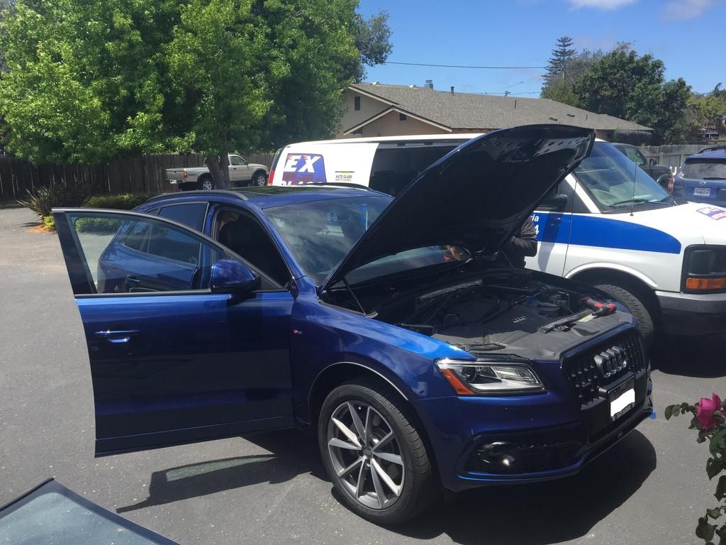
This is a DIY guide aimed at assisting anyone who is interested in retrofitting Active Lane Assist to a facelift (2013-2016) Q5/SQ5. This guide will be prohibitive to most as it does require changing the windshield. Additionally any retrofits you perform by following this guide you do so at your own risk. I assume no liability.
Coding the vehicle uses VCDS and a licensed VAG-COM cable from Ross-Tech. After all parts are finished being installed, the system must be calibrated by VAS-PC or ODIS (Offboard Diagnostic Information System). This is the actual system that the dealer uses. You can either take your vehicle to the dealer to have it calibrated, which consists of around 3-4 hours in labor (quoted by my SA), or you can make your own calibration board and do it yourself. Please note, I am unable to provide any assistance in in creating the calibration board. This means providing files, specs etc. The calibration board and design are considered copywritten material and I am therefore unable to distribute it, so please do not ask.
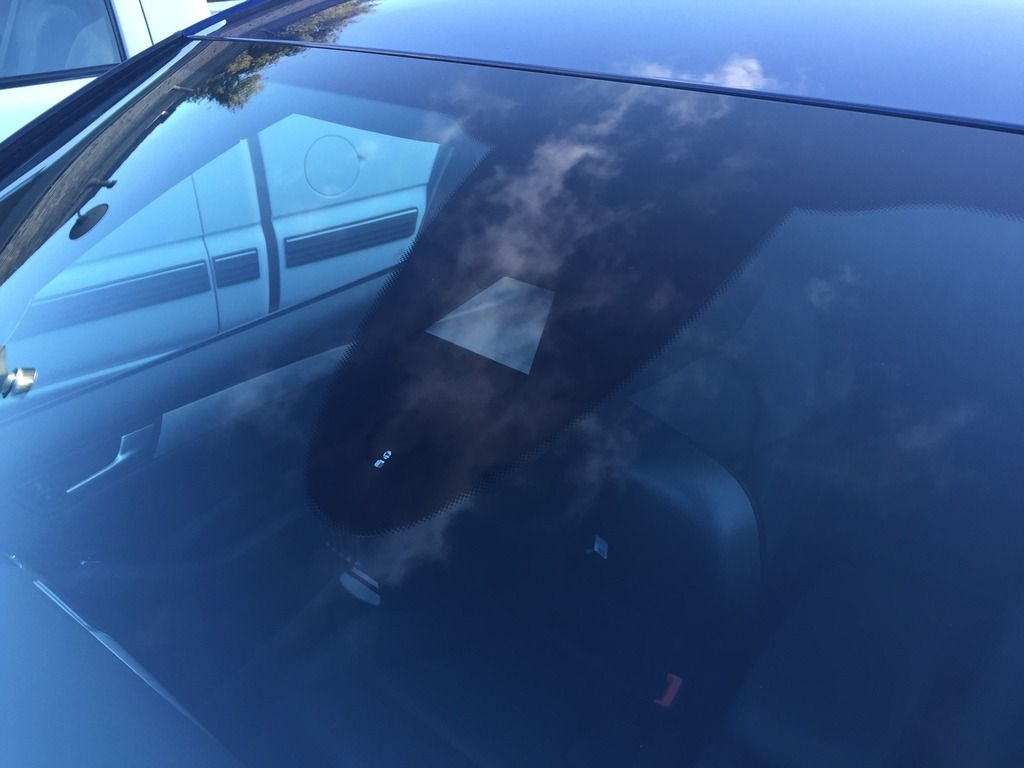
Active Lane Assist utilizes a gray scale camera in the upper center part of the windshield to analyze lane makings on the road and assist the vehicle to remain within them. If the vehicle starts to drift toward a lane marking, gentile steering corrections (no more than 3Nm of force) are given to assist the vehicle to stay within the lane. If the vehicle crosses over a lane-marking boundary, a steering wheel vibration is given to warn the driver.
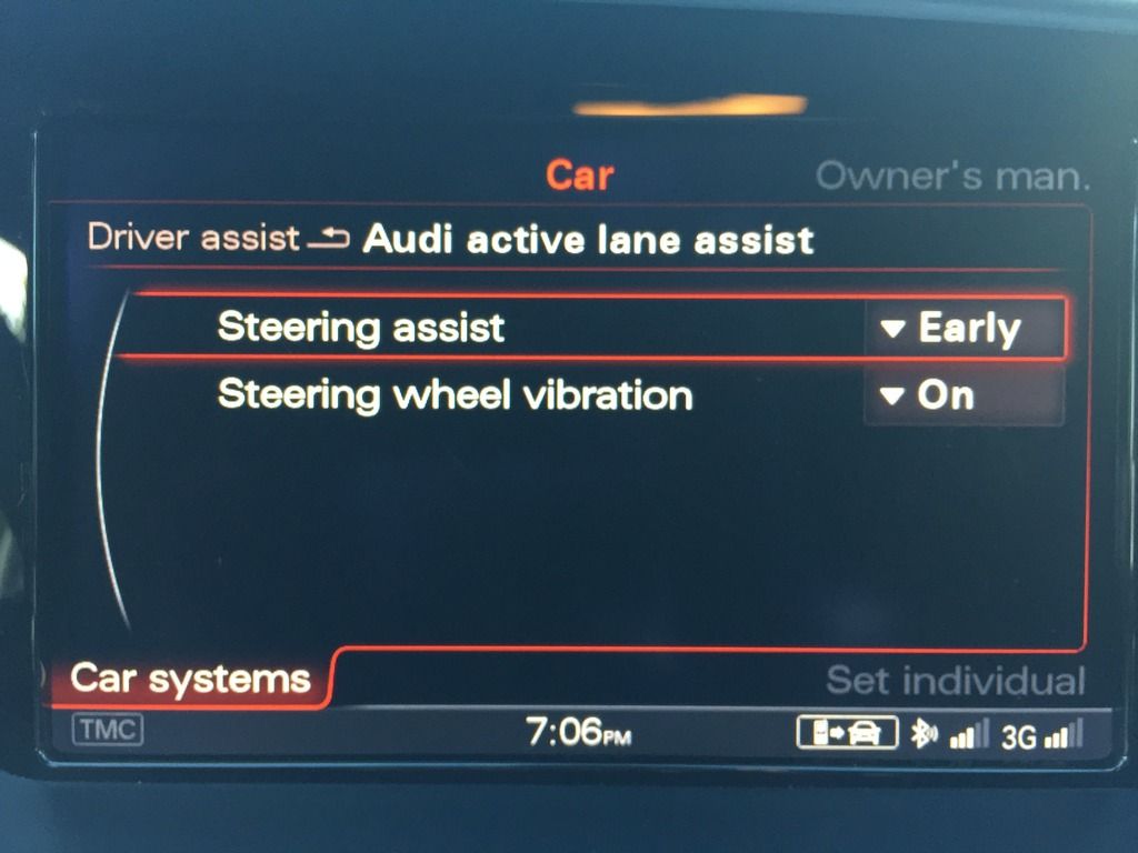
The system can be set in the MMI for “early” or “late” intervention. Within either setting, there is a buffer that the system sets between lane markings at which the system will not intervene. Choosing “early” just decreases the size of this buffer, but will not decrease it so much that it will keep the vehicle perfectly centered. WARNING - This system is considered a driving aide and is not advanced enough to simulate autonomous driving. If given the opportunity, the vehicle will inevitably bounce back and forth within the lane, or disable itself until your hands are placed back on the steering wheel which seems like a pretty smart driving habit to have.
From MY09-MY12 the system was just referred to as Audi Lane Assist. This previous system was not “active” and would not provide steering recommendations or interventions. It would only vibrate the steering wheel (by means of a vibration motor in the steering wheel itself) when the vehicle drifted out of its lane.
Active Lane Assist requires electromechanical power steering for the steering adjustments and steering wheel vibration. This could either be the regular electromechanical power steering or the optional Dynamic Steering. Unlike the previous generation that used a vibration motor in the steering wheel, this newer generation uses a harmonic whatchamacallit (I don’t know what its called) in the steering system to generate the vibration warning.
I only use genuine OE parts, and using heat shrink butt connectors makes all of the wire connections weather and corrosion resistant.
Parts List:
Windshield – 8R0 845 099 T NVB
Rain/Light sensor gel pad – 8U0 955 609
Cover for Camera – 4L0 907 299 AB
Transition cover from mirror to top cover – 4L0 907 299 AC
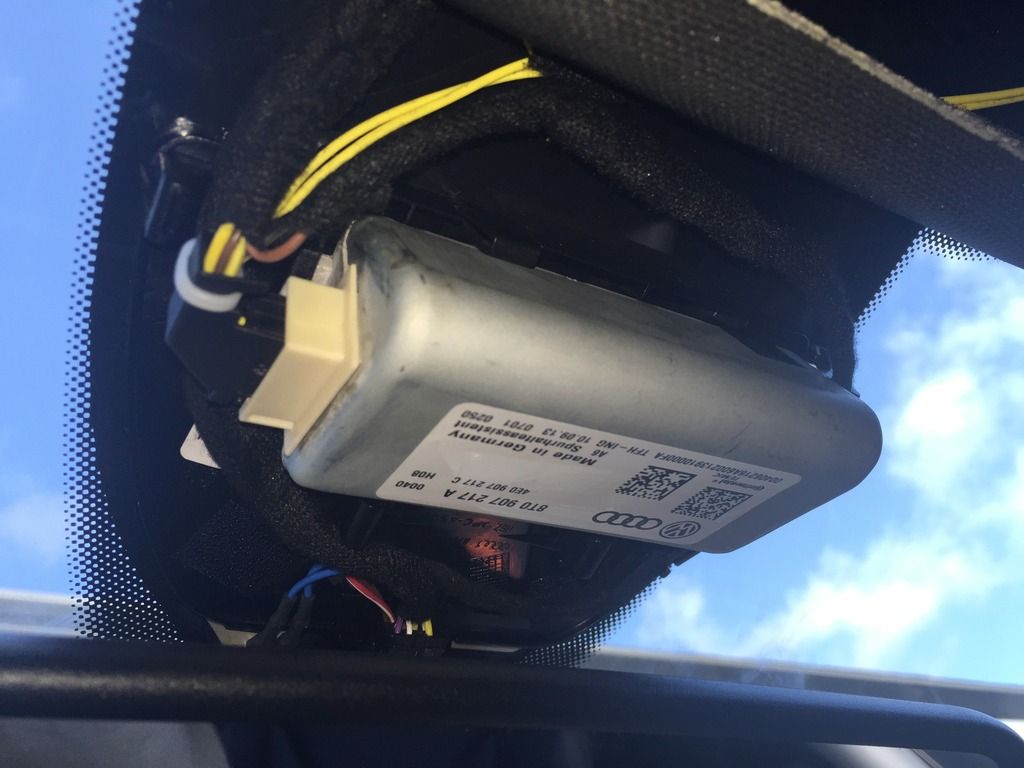
Gray scale Camera – 8T0 907 217 A
Note: 8K0 907 217 is for pre facelift and does not work on facelift models
Connector for Camera – 1J0 972 930 A
Connector for windscreen heater – 4B0 971 832
Repair wire – 000 979 009 E (4 of them for a total of 8 leads)
Steering Column Switch Assembly – 4G8 953 502 AL
Repair wire – 000 979 021 E
10A Fuse – N 017 131 11
Wiring harness fabric loom tape
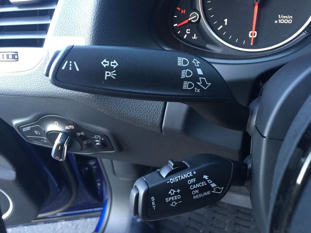
Section 1 – Changing of the Steering wheel levers.
Step 1 – Park vehicle on a flat surface and center your wheels and steering wheel.
Step 2 – Turn the car on only to the point of accessory power.
Step 3 – Disconnect the battery ground terminal while the vehicle is on in order to ensure a full power discharge from the airbag system.
Step 4 – Remove the Airbag from the steering wheel.
Step 5 – Remove the center bolt using a 12mm 12-point star (not torx) bit and remove the steering wheel. (Make sure you take note of the exact position of the steering wheel on the teeth of the steering column.
Step 6 – Remove the upper steering column cover.
Step 7 – Remove the lower steering column cover.
Step 8 – Disconnect the electrical connectors from the back of the switches and loosen the bolt, which holds the steering switches to the column itself.
Step 9 – Remove the steering column multi-switch assembly.
Your new steering column switches, if purchased from the dealer, will not come with the steering column clock spring control module (8K0 953 568 M). If you purchased a set of switches that came with one, I recommend you switch it out for your existing one so you can avoid having to re perform steering and calibration, end stops learning, or dynamic steering basic settings. If the clock spring control module in your vehicle already does not support the coding of lane assist (error 31 - rejected), then the steering angle calibration procedures will be unavoidable.
Reinstall the new steering column multi-switch with the Active Lane Assist button on the end of the turn signal lever. Installation is reverse of removal. The steering wheel bolt must be tightened to 30Nm + 90 degrees.
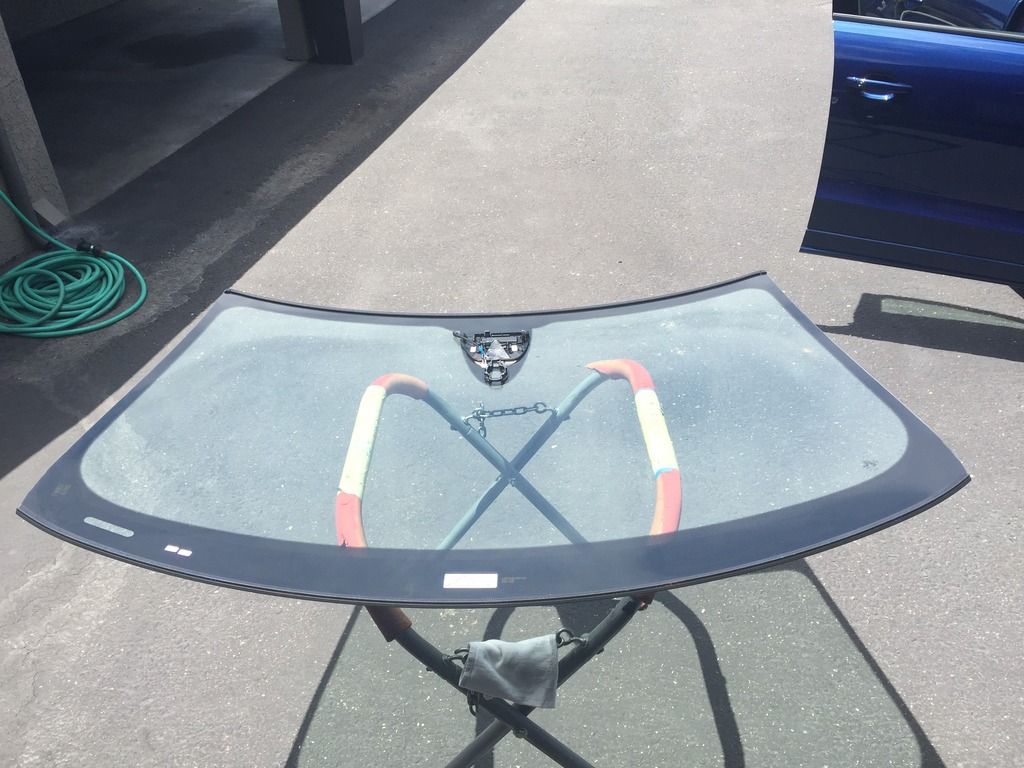
Section 2 – Change the windshield
Step 1 – Call someone else to do it.
Step 2 – Its Done!
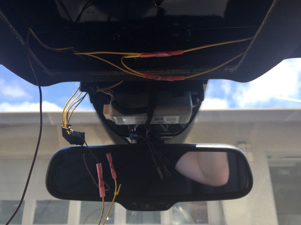
Section 3 – Camera wiring harness.
Step 1 - Remove the driver’s side and passenger side A-pillars.
Step 2 - Remove the passenger side lower A-Pillar kick panel.
Step 3 - Remove both sun visors, visor clips and grab handles.
Step 5 - Remove the overhead light/sunroof/sunglass holder assembly.
Step 6 – Remove the driver’s side instrument panel fuse cover.
Step 7 – Remove the driver’s side lower instrument panel cover.
Step 8 – Disengage the fuse relay plate from the metal instrument panel frame.
Step 9 – Remove ST1 from the fuse plate and insert repair wire 000 979 021 E into space #4 (SC4). Reinstall fuse block into plate and reattach plate to instrument panel frame. Crimp new wire for power onto the new repair wire coming out of the fuse block.
Step10 – Crimp Ring terminal on end of ground wire and attach to instrument panel frame anchor bolt behind the fuse block assembly.
Step 11 – Size both wires appropriately to run from fuse panel area to where camera on windshield will go routing up the A-pillar and through the headliner. Wrap both wires in fabric loom tape and then secure along existing harness in a-pillar. IMPORTANT: do not interfere with the red crash sensor.
Step 12 – Locate connector 5 on the passenger side relay plate behind the lower a-pillar kick panel. Tap two new wires for the Extended-CAN system into the wires on pin 7 and pin 8. These wires should be OR/BR and OR/GY.
Step 13 - Size both wires appropriately to run from the kick panel area to where camera on windshield will go routing up the A-pillar and through the headliner. Wrap both wires in fabric loom tape and then secure along existing harness in a-pillar.
IMPORTANT: do not interfere with the red crash sensor.
Step 14 – Insert 5 repair wires (000 979 009 E) into the camera connector 1J0 972 930 A (pins 1, 2, 4, 6 and 9). Note – Insert a whole repair wire uncut into pin 6, as the other end will go into the connector for the windscreen heater.
Step 15 – Attach power wire from fuse block to pin 1.
Step 16 – Attach ground wire from fuse block to pin 2 and an additional repair wire 000 979 009 E which will go to the windscreen heater.
Step 17 – Attach CAN wire OR/BR from pin 7 on relay plate connector 5 to camera connector pin 4.
Step 18 – Attach CAN wire OR/GY from pin 8 on relay plate connector 5 to camera connector pin 9. Note – This is a great time to install Highbeam assist as it uses these same two CAN wires.
Step 19 – Insert extra ground repair wire out of camera connector pin 2 into windscreen heater connector pin 2(4B0 971 832).
Step 20 – Insert power wire from camera connector pin 6 to windscreen heater connector pin 1.
Step 21 – Tape everything up with loom tape. This is the hard part making it look pretty.
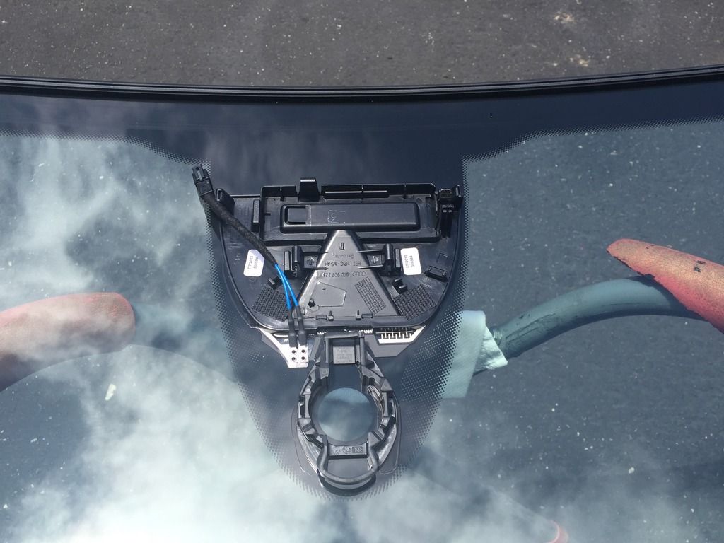
Section 4 – Install camera onto windshield
Step 1 – Install the camera 8T0 907 217 A into the holder on the windshield. Install the new connector into the side of it and also attach the new windscreen heater connector onto the windscreen heater, which is fixed to the glass from the factory.
Step 2 – Re-Attach the rain/light sensor with brand new gel pad. You must use a new one or it wont work properly.
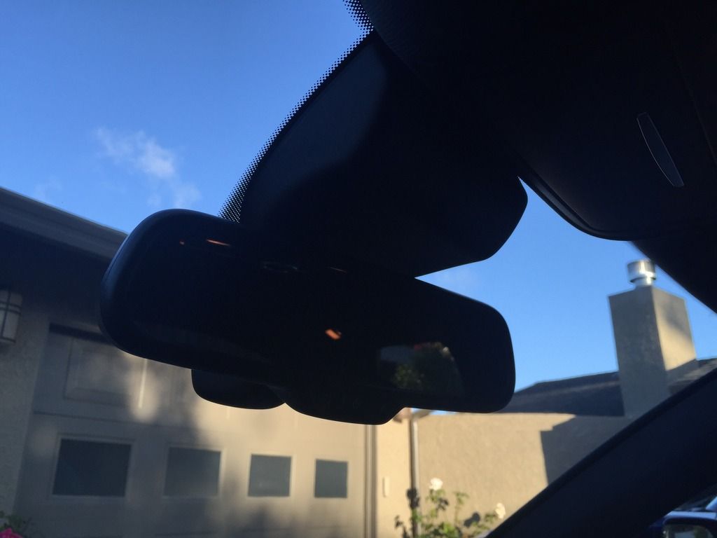
Step 3 – Re-attach the interior rearview mirror (highbeam assist if you are doing that at the same time).
Step 4 – Attach new transition cap 4L0 907 299 AC to mirror housing.
Step 5 – Attach new camera cover cap 4L0 907 299 AB.
Section 5 – Camera Coding
VCDS needed with a licensed VAG-COM cable. The following coding structure is used for the Audi Q5:
7 positions – 7654321
Positions 1&2 – Model
Audi Q5 – 04
Audi A4 – 01
Audi A5 – 02
Position 3 – Region
0 – Rest of world
1 – Only USA
2 – Only Great Britain
3 – Only Japan
Note: If you use “1-Only USA” then you will only have access to the steering wheel vibration setting in the MMI. If you select “0 – Rest of world” then you will have access to the steering wheel vibration setting in addition to “early” and “late” intervention settings. I chose the latter of the two.
Position 4 – Options
0 – Without adaptive suspension/without adaptive cruise control.
1 – With adaptive suspension/without adaptive cruise control.
2 – Without adaptive suspension/with adaptive cruise control.
3 – With adaptive suspension/with adaptive cruise control.
Position 5 – Options
0 – Without Active Steering (PR-1N8)/without navigation.
1 – With Active Steering (PR-1N8)/without navigation.
2 – Without Active Steering (PR-1N8)/with navigation.
3 – With Active Steering (PR-1N8)/with navigation.
Positions 6&7 – OE Trailer provisions
00 – No trailer provisions installed.
01 – Trailer Provisions installed.
Section 6 – Coding the rest of the vehicle using VCDS.
Note: If you attempt to code a module and get a 31-Rejected error, your module either doesn't support the feature (thus needing to change to the correct control module/hardware), or you have conflicting coding int he module that it cannot interpret.
Step 1 – Access 19-Can Gateway>Installation List. Check 5C-Lane Maintainence. Save Coding.
Step 2 – Access 17-Instruments>07 Coding>Long Coding Helper>Byte 4 Bit 6 change to 1. (This is not labeled in VCDS and you will have to change the binary manually)
Step 3 – Access 16-Steering Wheel>07 Coding>Long Coding Helper>Byte 2 Bit 7 change to 1 (This is labeled). And Byte 2 Bit 6 change to 1 (This is not labeled and you will have to change the binary manually). This tells the system active lane assist with heading control is installed but there isn’t a vibration motor in the wheel. If you do not change bit 6 then the system will give you a vibration motor error.
Step 4 – Access 44-Steering Assist>07 Coding>Long Coding Helper>Byte 2 Bit 0 change to 1.
Step 5 – Enter the hidden menu on the MMI to activate the menu system for Active Lane Assist
Step 6 – Car>Cardevicelist>Check “Lane Departure Warning”
Step 7 – Car>Carmenuoperation>Lane Departure Warning – Change from 0 to 5
Section 7 – Calibrating
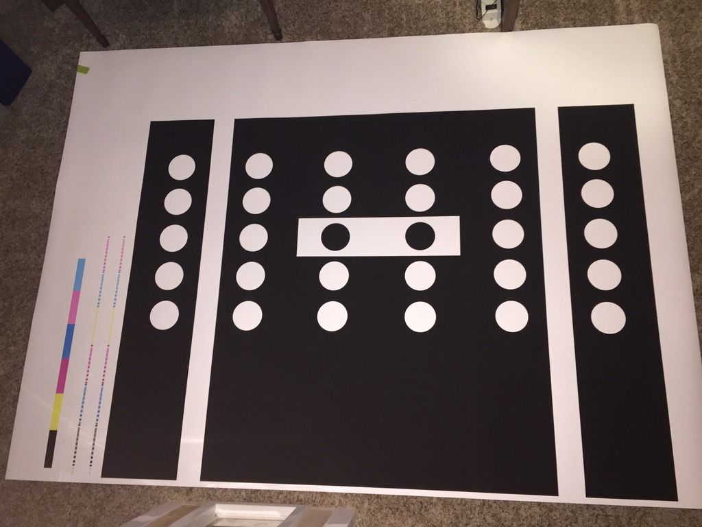
It is a better choice to have this done at the dealer due to the tools and degree of precision required to calibrate the system properly, but for the sake of information, Ill explain how the process works. VAS-PC or ODIS 2.0, a VAS5054(a) and a VAS6430 are required to calibrate the system. The specs of the VAS6430 can be found online (no I cannot tell you where) and recreated with a vector based graphics program. This board is EXTREMELY PRECISE and it is of the utmost importance that you are as accurate as you can. You are dealing with calibrating a camera that identifies lane markings on the road. Let that one sink in for a minute… The board must be attached to a stand that can be adjusted on all three axis.
Placing the board: Elsa will say the panel must be centered in front of the vehicle and give the distance the calibration board must be from the central axis of the front wheels (150cm), but it does not give the height value. I have found a couple other forums where some individuals had done this retrofit outside of the country. Each one I read had a different opinion on how to do the height of the panel such as:
- Bottom of the board at the same exact height as the wheel arch of the front fenders.
- Central point of the central white rectangle at the same exact physical height of the camera on the car.
- Central point of the central white rectangle 120cm off the floor regardless of the height of the vehicle.
None of these proved to be entirely correct. Two of them would calibrate, but they would calibrate improperly and the car wouldn’t adhere to the lane markings correctly. The third option caused the camera to not recognize lane markings at all.
The dealer’s alignment computer calculates the optimum height value of the calibration panel. It is based on a combination of vehicle model, fender heights (4) and wheel base. Assuming the vehicle is on the floor and not on an alignment stand, The Q5’s calibration board starts at a base height of 140cm from the floor to the center of the white rectangle on the VAS6430. The A4/A5’s start at a base height of 120cm from the floor to the center of the white rectangle. When the vehicle is on an alignment rack, the distance from the contact point of the tires to the floor is added to that value. The heights of the 4 fenders affect the pitch of the camera but that calculation is done in the camera as well as the alignment computer. that pitch will add or subtract centimeters from the base height. It may affect it only a few centimeters, but its enough to cause the camera to not see far enough or lose track of lane markings going up or down hills. Doing a mock calibration first will give the optimum panel height value in the measurement blocks of the camera. Once the panel height is adjusted to this value, the calibration procedure is then run again. Doing the calibration procedure at home will get the system close to where it needs to be and also clear the No Basic Settings error, but it will never be precise enough.
Procedure:
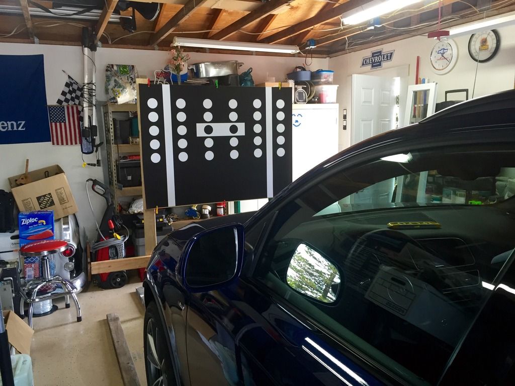
Step 1 – Perform a mock calibration - Place the VAS6430 perfectly center in front of the vehicle. Set it so that the bottom of the panel is around the same height as the bottom lip of the fender. Don’t worry about making sure the panel is centered, perfectly straight or even the right distance from the car. You just want it to be in front of the camera.
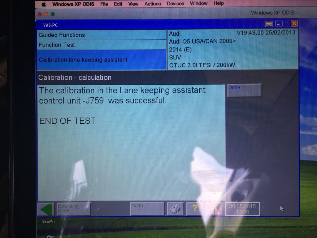
Step 2 – Enter VAS-PC or ODIS/Guided Functions/5C-Lane Maintain/Calibration and run through the procedure. It will ask you for the wheel arch height of all 4 wheels in mm. It will then calibrate in less than a minute. You are not done! This is not the real calibration.
Step 3 – Read measuring block #21/Section 4. This number is the “Calibrated height” of the camera. This value was calculated based on the model of the vehicle, the heights of all 4 wheel arches, and the now known pitch of the camera. The height of the panel during the mock calibration has nothing to do with determining this number. Based on my wheel arch height of 819mm, after running the mock calibration it determined my camera has a “calibrated height” of 1468mm (146CM).
Step 4 – Align your panel on your stand so that the center of the white rectangle with the two black circles is PRECISELY the same height as your “calibrated height” as determined above. Everything must be perfectly level!
Step 5 – The calibration board must be 150CM ± 2cm from the central axis of the front wheels.
Step 6 – The calibration board must be perfectly centered in front of the car.
ONCE AGAIN! I CANNOT STRESS HOW IMPORTANT-SAFETY WISE-HOW ACCURATE THESE MEASUREMENTS MUST BE!!!
Step 7 – Again, enter VAS-PC or ODIS/Guided Functions/5C-Lane Maintain/Calibration and run through the procedure. It will ask you for the wheel arch height of all 4 wheels in mm. It will then calibrate in less than a minute.
If all shows successful, then you are done calibrating.
Clear all faults and refresh the system. No errors should be present.
Even after calibrating the system myself, I still went back to the dealer to have it done as I could not get it to be as accurate as it should be. The factory VAS6430 calibration panel, although centered in front of the car, has a micro adjustment knob on the back that tilts the panel on the vertical axis to match the same angle of the rear axle of the vehicle. Although seemingly straight, when the rear axle is bolted into the car at the factory, it may be a few millimeters off. This is the same reason 4 wheel alignments exist. The panel must be perfectly parallel to the rear axle of the car. The camera has an on-line calibration mode that runs where it self calibrates the pitch, yaw, and roll, as it is being used. This is done in the background unbeknownst to the driver of the car. It may not be perfectly accurate at first, so you need to drive with it on for about 20km until the cameras internal gyroscope makes its own necessary adjustments.
Special thanks to Ross-Tech and Robyscom over at audirsclub.it
Coding the vehicle uses VCDS and a licensed VAG-COM cable from Ross-Tech. After all parts are finished being installed, the system must be calibrated by VAS-PC or ODIS (Offboard Diagnostic Information System). This is the actual system that the dealer uses. You can either take your vehicle to the dealer to have it calibrated, which consists of around 3-4 hours in labor (quoted by my SA), or you can make your own calibration board and do it yourself. Please note, I am unable to provide any assistance in in creating the calibration board. This means providing files, specs etc. The calibration board and design are considered copywritten material and I am therefore unable to distribute it, so please do not ask.
Active Lane Assist utilizes a gray scale camera in the upper center part of the windshield to analyze lane makings on the road and assist the vehicle to remain within them. If the vehicle starts to drift toward a lane marking, gentile steering corrections (no more than 3Nm of force) are given to assist the vehicle to stay within the lane. If the vehicle crosses over a lane-marking boundary, a steering wheel vibration is given to warn the driver.
The system can be set in the MMI for “early” or “late” intervention. Within either setting, there is a buffer that the system sets between lane markings at which the system will not intervene. Choosing “early” just decreases the size of this buffer, but will not decrease it so much that it will keep the vehicle perfectly centered. WARNING - This system is considered a driving aide and is not advanced enough to simulate autonomous driving. If given the opportunity, the vehicle will inevitably bounce back and forth within the lane, or disable itself until your hands are placed back on the steering wheel which seems like a pretty smart driving habit to have.
From MY09-MY12 the system was just referred to as Audi Lane Assist. This previous system was not “active” and would not provide steering recommendations or interventions. It would only vibrate the steering wheel (by means of a vibration motor in the steering wheel itself) when the vehicle drifted out of its lane.
Active Lane Assist requires electromechanical power steering for the steering adjustments and steering wheel vibration. This could either be the regular electromechanical power steering or the optional Dynamic Steering. Unlike the previous generation that used a vibration motor in the steering wheel, this newer generation uses a harmonic whatchamacallit (I don’t know what its called) in the steering system to generate the vibration warning.
I only use genuine OE parts, and using heat shrink butt connectors makes all of the wire connections weather and corrosion resistant.
Parts List:
Windshield – 8R0 845 099 T NVB
Rain/Light sensor gel pad – 8U0 955 609
Cover for Camera – 4L0 907 299 AB
Transition cover from mirror to top cover – 4L0 907 299 AC
Gray scale Camera – 8T0 907 217 A
Note: 8K0 907 217 is for pre facelift and does not work on facelift models
Connector for Camera – 1J0 972 930 A
Connector for windscreen heater – 4B0 971 832
Repair wire – 000 979 009 E (4 of them for a total of 8 leads)
Steering Column Switch Assembly – 4G8 953 502 AL
Repair wire – 000 979 021 E
10A Fuse – N 017 131 11
Wiring harness fabric loom tape
Section 1 – Changing of the Steering wheel levers.
Step 1 – Park vehicle on a flat surface and center your wheels and steering wheel.
Step 2 – Turn the car on only to the point of accessory power.
Step 3 – Disconnect the battery ground terminal while the vehicle is on in order to ensure a full power discharge from the airbag system.
Step 4 – Remove the Airbag from the steering wheel.
Step 5 – Remove the center bolt using a 12mm 12-point star (not torx) bit and remove the steering wheel. (Make sure you take note of the exact position of the steering wheel on the teeth of the steering column.
Step 6 – Remove the upper steering column cover.
Step 7 – Remove the lower steering column cover.
Step 8 – Disconnect the electrical connectors from the back of the switches and loosen the bolt, which holds the steering switches to the column itself.
Step 9 – Remove the steering column multi-switch assembly.
Your new steering column switches, if purchased from the dealer, will not come with the steering column clock spring control module (8K0 953 568 M). If you purchased a set of switches that came with one, I recommend you switch it out for your existing one so you can avoid having to re perform steering and calibration, end stops learning, or dynamic steering basic settings. If the clock spring control module in your vehicle already does not support the coding of lane assist (error 31 - rejected), then the steering angle calibration procedures will be unavoidable.
Reinstall the new steering column multi-switch with the Active Lane Assist button on the end of the turn signal lever. Installation is reverse of removal. The steering wheel bolt must be tightened to 30Nm + 90 degrees.
Section 2 – Change the windshield
Step 1 – Call someone else to do it.
Step 2 – Its Done!
Section 3 – Camera wiring harness.
Step 1 - Remove the driver’s side and passenger side A-pillars.
Step 2 - Remove the passenger side lower A-Pillar kick panel.
Step 3 - Remove both sun visors, visor clips and grab handles.
Step 5 - Remove the overhead light/sunroof/sunglass holder assembly.
Step 6 – Remove the driver’s side instrument panel fuse cover.
Step 7 – Remove the driver’s side lower instrument panel cover.
Step 8 – Disengage the fuse relay plate from the metal instrument panel frame.
Step 9 – Remove ST1 from the fuse plate and insert repair wire 000 979 021 E into space #4 (SC4). Reinstall fuse block into plate and reattach plate to instrument panel frame. Crimp new wire for power onto the new repair wire coming out of the fuse block.
Step10 – Crimp Ring terminal on end of ground wire and attach to instrument panel frame anchor bolt behind the fuse block assembly.
Step 11 – Size both wires appropriately to run from fuse panel area to where camera on windshield will go routing up the A-pillar and through the headliner. Wrap both wires in fabric loom tape and then secure along existing harness in a-pillar. IMPORTANT: do not interfere with the red crash sensor.
Step 12 – Locate connector 5 on the passenger side relay plate behind the lower a-pillar kick panel. Tap two new wires for the Extended-CAN system into the wires on pin 7 and pin 8. These wires should be OR/BR and OR/GY.
Step 13 - Size both wires appropriately to run from the kick panel area to where camera on windshield will go routing up the A-pillar and through the headliner. Wrap both wires in fabric loom tape and then secure along existing harness in a-pillar.
IMPORTANT: do not interfere with the red crash sensor.
Step 14 – Insert 5 repair wires (000 979 009 E) into the camera connector 1J0 972 930 A (pins 1, 2, 4, 6 and 9). Note – Insert a whole repair wire uncut into pin 6, as the other end will go into the connector for the windscreen heater.
Step 15 – Attach power wire from fuse block to pin 1.
Step 16 – Attach ground wire from fuse block to pin 2 and an additional repair wire 000 979 009 E which will go to the windscreen heater.
Step 17 – Attach CAN wire OR/BR from pin 7 on relay plate connector 5 to camera connector pin 4.
Step 18 – Attach CAN wire OR/GY from pin 8 on relay plate connector 5 to camera connector pin 9. Note – This is a great time to install Highbeam assist as it uses these same two CAN wires.
Step 19 – Insert extra ground repair wire out of camera connector pin 2 into windscreen heater connector pin 2(4B0 971 832).
Step 20 – Insert power wire from camera connector pin 6 to windscreen heater connector pin 1.
Step 21 – Tape everything up with loom tape. This is the hard part making it look pretty.
Section 4 – Install camera onto windshield
Step 1 – Install the camera 8T0 907 217 A into the holder on the windshield. Install the new connector into the side of it and also attach the new windscreen heater connector onto the windscreen heater, which is fixed to the glass from the factory.
Step 2 – Re-Attach the rain/light sensor with brand new gel pad. You must use a new one or it wont work properly.
Step 3 – Re-attach the interior rearview mirror (highbeam assist if you are doing that at the same time).
Step 4 – Attach new transition cap 4L0 907 299 AC to mirror housing.
Step 5 – Attach new camera cover cap 4L0 907 299 AB.
Section 5 – Camera Coding
VCDS needed with a licensed VAG-COM cable. The following coding structure is used for the Audi Q5:
7 positions – 7654321
Positions 1&2 – Model
Audi Q5 – 04
Audi A4 – 01
Audi A5 – 02
Position 3 – Region
0 – Rest of world
1 – Only USA
2 – Only Great Britain
3 – Only Japan
Note: If you use “1-Only USA” then you will only have access to the steering wheel vibration setting in the MMI. If you select “0 – Rest of world” then you will have access to the steering wheel vibration setting in addition to “early” and “late” intervention settings. I chose the latter of the two.
Position 4 – Options
0 – Without adaptive suspension/without adaptive cruise control.
1 – With adaptive suspension/without adaptive cruise control.
2 – Without adaptive suspension/with adaptive cruise control.
3 – With adaptive suspension/with adaptive cruise control.
Position 5 – Options
0 – Without Active Steering (PR-1N8)/without navigation.
1 – With Active Steering (PR-1N8)/without navigation.
2 – Without Active Steering (PR-1N8)/with navigation.
3 – With Active Steering (PR-1N8)/with navigation.
Positions 6&7 – OE Trailer provisions
00 – No trailer provisions installed.
01 – Trailer Provisions installed.
Section 6 – Coding the rest of the vehicle using VCDS.
Note: If you attempt to code a module and get a 31-Rejected error, your module either doesn't support the feature (thus needing to change to the correct control module/hardware), or you have conflicting coding int he module that it cannot interpret.
Step 1 – Access 19-Can Gateway>Installation List. Check 5C-Lane Maintainence. Save Coding.
Step 2 – Access 17-Instruments>07 Coding>Long Coding Helper>Byte 4 Bit 6 change to 1. (This is not labeled in VCDS and you will have to change the binary manually)
Step 3 – Access 16-Steering Wheel>07 Coding>Long Coding Helper>Byte 2 Bit 7 change to 1 (This is labeled). And Byte 2 Bit 6 change to 1 (This is not labeled and you will have to change the binary manually). This tells the system active lane assist with heading control is installed but there isn’t a vibration motor in the wheel. If you do not change bit 6 then the system will give you a vibration motor error.
Step 4 – Access 44-Steering Assist>07 Coding>Long Coding Helper>Byte 2 Bit 0 change to 1.
Step 5 – Enter the hidden menu on the MMI to activate the menu system for Active Lane Assist
Step 6 – Car>Cardevicelist>Check “Lane Departure Warning”
Step 7 – Car>Carmenuoperation>Lane Departure Warning – Change from 0 to 5
Section 7 – Calibrating
It is a better choice to have this done at the dealer due to the tools and degree of precision required to calibrate the system properly, but for the sake of information, Ill explain how the process works. VAS-PC or ODIS 2.0, a VAS5054(a) and a VAS6430 are required to calibrate the system. The specs of the VAS6430 can be found online (no I cannot tell you where) and recreated with a vector based graphics program. This board is EXTREMELY PRECISE and it is of the utmost importance that you are as accurate as you can. You are dealing with calibrating a camera that identifies lane markings on the road. Let that one sink in for a minute… The board must be attached to a stand that can be adjusted on all three axis.
Placing the board: Elsa will say the panel must be centered in front of the vehicle and give the distance the calibration board must be from the central axis of the front wheels (150cm), but it does not give the height value. I have found a couple other forums where some individuals had done this retrofit outside of the country. Each one I read had a different opinion on how to do the height of the panel such as:
- Bottom of the board at the same exact height as the wheel arch of the front fenders.
- Central point of the central white rectangle at the same exact physical height of the camera on the car.
- Central point of the central white rectangle 120cm off the floor regardless of the height of the vehicle.
None of these proved to be entirely correct. Two of them would calibrate, but they would calibrate improperly and the car wouldn’t adhere to the lane markings correctly. The third option caused the camera to not recognize lane markings at all.
The dealer’s alignment computer calculates the optimum height value of the calibration panel. It is based on a combination of vehicle model, fender heights (4) and wheel base. Assuming the vehicle is on the floor and not on an alignment stand, The Q5’s calibration board starts at a base height of 140cm from the floor to the center of the white rectangle on the VAS6430. The A4/A5’s start at a base height of 120cm from the floor to the center of the white rectangle. When the vehicle is on an alignment rack, the distance from the contact point of the tires to the floor is added to that value. The heights of the 4 fenders affect the pitch of the camera but that calculation is done in the camera as well as the alignment computer. that pitch will add or subtract centimeters from the base height. It may affect it only a few centimeters, but its enough to cause the camera to not see far enough or lose track of lane markings going up or down hills. Doing a mock calibration first will give the optimum panel height value in the measurement blocks of the camera. Once the panel height is adjusted to this value, the calibration procedure is then run again. Doing the calibration procedure at home will get the system close to where it needs to be and also clear the No Basic Settings error, but it will never be precise enough.
Procedure:
Step 1 – Perform a mock calibration - Place the VAS6430 perfectly center in front of the vehicle. Set it so that the bottom of the panel is around the same height as the bottom lip of the fender. Don’t worry about making sure the panel is centered, perfectly straight or even the right distance from the car. You just want it to be in front of the camera.
Step 2 – Enter VAS-PC or ODIS/Guided Functions/5C-Lane Maintain/Calibration and run through the procedure. It will ask you for the wheel arch height of all 4 wheels in mm. It will then calibrate in less than a minute. You are not done! This is not the real calibration.
Step 3 – Read measuring block #21/Section 4. This number is the “Calibrated height” of the camera. This value was calculated based on the model of the vehicle, the heights of all 4 wheel arches, and the now known pitch of the camera. The height of the panel during the mock calibration has nothing to do with determining this number. Based on my wheel arch height of 819mm, after running the mock calibration it determined my camera has a “calibrated height” of 1468mm (146CM).
Step 4 – Align your panel on your stand so that the center of the white rectangle with the two black circles is PRECISELY the same height as your “calibrated height” as determined above. Everything must be perfectly level!
Step 5 – The calibration board must be 150CM ± 2cm from the central axis of the front wheels.
Step 6 – The calibration board must be perfectly centered in front of the car.
ONCE AGAIN! I CANNOT STRESS HOW IMPORTANT-SAFETY WISE-HOW ACCURATE THESE MEASUREMENTS MUST BE!!!
Step 7 – Again, enter VAS-PC or ODIS/Guided Functions/5C-Lane Maintain/Calibration and run through the procedure. It will ask you for the wheel arch height of all 4 wheels in mm. It will then calibrate in less than a minute.
If all shows successful, then you are done calibrating.
Clear all faults and refresh the system. No errors should be present.
Even after calibrating the system myself, I still went back to the dealer to have it done as I could not get it to be as accurate as it should be. The factory VAS6430 calibration panel, although centered in front of the car, has a micro adjustment knob on the back that tilts the panel on the vertical axis to match the same angle of the rear axle of the vehicle. Although seemingly straight, when the rear axle is bolted into the car at the factory, it may be a few millimeters off. This is the same reason 4 wheel alignments exist. The panel must be perfectly parallel to the rear axle of the car. The camera has an on-line calibration mode that runs where it self calibrates the pitch, yaw, and roll, as it is being used. This is done in the background unbeknownst to the driver of the car. It may not be perfectly accurate at first, so you need to drive with it on for about 20km until the cameras internal gyroscope makes its own necessary adjustments.
Special thanks to Ross-Tech and Robyscom over at audirsclub.it
Last edited:
")
 i can confirm that the excellent DIY from Mrclopec
  also works with minor part number adjustments for windshield and rear mirror trim on Audi A5 Cabrio 2012/13 FL - assuming you have