Hi again jack,
I have replaced the sensors and used a meter to test the continuity back to the to ensure there are no breaks in the wires and all is good there No breaks anywhere. I’m new to is there a function in it that can show the signal/output from the sensors?
Many thanks Gary
Gary: I'm reading your responses to with interest and I'm looking at patterns in the in your auto-scan - and I'm puzzled (which is not an unusual condition these days given my age and my fondness for single malt scotch
")
)!
At least for the in your scan report, and with the caveat that any observation made on the opposite side of the world is necessarily limited in accuracy, there is a commonality in the sensor errors. I'm not sure how familiar you are with these sensors and I apologize in advance if you already know this stuff, but the 3 x sensors in error on the are basically 3 x pin devices that take their power from a 5 Volt supply within the hex01 module.
Basically, the sensors are wired like this:
Despite that fact that Hall effect transducers can be of various different types (digital/analogue, bipolar/unipolar etc.), their simplicity from an external wiring perspective does make fault finding easier .
I don't have access to the for your particular CJXC engine, but I doubt that ALL 3 x sensors will take their +5V power from the same pin on the (albeit, I acknowledge that it is possible).
Also, it's tempting to conclude that the +5V power circuit within the is "cactus", but if this were the case, I suspect that there would be many, many more as there are numerous other like-powered transducers in the vehicle - unless of course, if the failure has occurred downstream of a circuit distribution point within the module housing.
So - to add to Jack's sage advice, perhaps after you have sourced the , grab a multi-meter (with a high internal impedance) and measure the +5V rail on the supply pins for the 3 x sensors - maybe?
Don
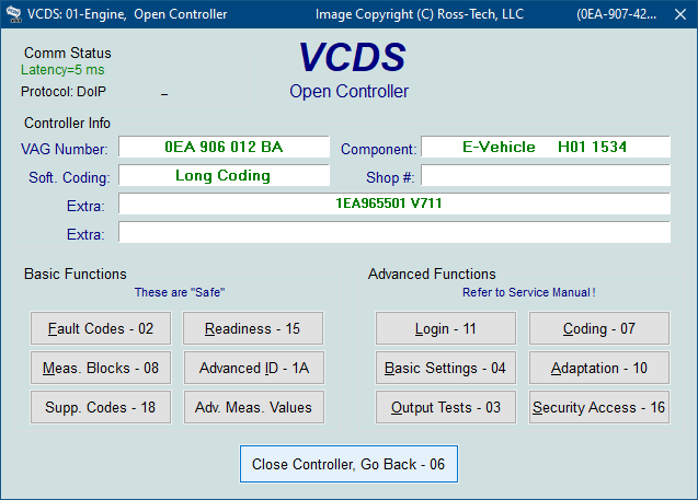
PS: as for your question about being able to measure sensor outputs, yes there is such a facility. It's done by selecting the
Adv. Meas. Value option from the screen:
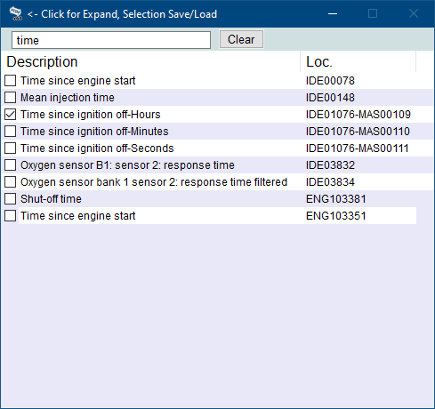
For your module, you will then need to enter a suitable descriptor in the search box (see upper LHS of picture below) to identify the correct transducer - then place a tick in the box:


 :rolleyes:")
")