8E0909518AL (BFB) 1.8T Soft Coding & Other Tweaks for a Retrofit

   #1  

nugentp

Verified VCDS User
Verified
Joined
Jan 3, 2019
Messages
1,033
Reaction score
582
Location
UK
VCDS Serial number
C?ID=6386
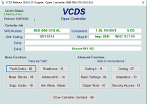
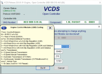
I got asked to look into some other retrofit project with a longitudinal 1.8T destined for a B3/B4 platform of old... that came long before CAN Bus and such like so I have some ME7 pokery to look forward to. I sourced an unsullied BFB ECU very cheaply 8E0 909 518 AL as shown below. One thing stood out is the ECU has last soft coding digit of 4 when VCDS helper suggests only 1 is valid for the B6 platform.

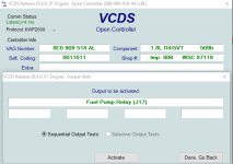
After extracting the EEPROM contents (on the bench in boot mode) I grabbed the VIN and checked it on PL24 - transpires its a B6 Cabrio (8H) from 2005 with this motor - am I right in saying the last soft coding digit of 4 would rightly reflect the Cabrio ?
1789505129989.png

I have since changed soft coding to 0011011 to reflect something closer to its new home in a B3/B4 chassis as that stops it nagging about expected ASR conversations with the ABS... obviously it still nags about missing messages from cluster & HVAC but I have a cunning plan to resolve those in the bowels of CAN config masks... helps to have a really accurate KP file for the Rev0005 flash that I have since loaded into this ECU so I can explore more ME7.5 architectural wonderment as I go.

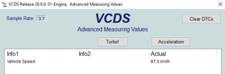
I have already managed to get this ECU to ignore expectation for VSS input from CAN Bus and using the legacy discrete pin for that input - works perfectly with scaling params defined for pulses per km so this can be made deadly accurate when calibrated against a GPS. Screen shot below with 100Hz VSS input and OE scaling of 4131 pulses/km. B3/B4 cluster generates VSS signal from the mechanical G22 sensor on the gearbox.

Vehicle Speed = 100 (VSS Hz) * 3600 (seconds per hr) / 4131 (pulses per km) = 87.15kph
1789506150180.png

There was another fault code with expectation for J527/SWC messages, but I figured that was for cruise control (pin 38) so with VCDS in coding-2, I was able to enter the helper code to disable CCS and that has cleared that fault.

The ECU is still looking for the discrete airbag controller 'crash' signal - that fault goes away when correct PWM signal is applied (pin 67), but I want to find the right codeword parameter in flash so that it ignores that pin entirely as it won't exist on the B3/BV4 platform.

The B3/B4 cluster is expecting a discrete RPM signal so I know where that comes from in 'legacy mode' with another pin that doesn't get called out on the BFB schematic. I need to verify that on the bench with my Arduino 60-2 flywheel signal generator code to provide a G28 input. I can simulate G40 in correct phasing as well on the bench so its possible to fake this thing into thinking its in sync and able to generate sparks etc - subject to however many other active faults on the bench need to be masked, but I don't need to go that far.

Thank you Mr Bosch for leaving these 'old school' methods and pins enabled on the more modern ECUs so they can be persuaded to work with older cars without having to do open brain surgery.
 
Last edited:
   #2  

Zenerdiode

Verified VCDS User
Verified
Joined
Jun 26, 2014
Messages
1,559
Reaction score
2,316
Location
Newcastle, England
VCDS Serial number
C?ID=24330
obviously it still nags about missing messages from cluster & HVAC but I have a cunning plan to resolve those in the bowels of CAN config masks...

If you have a definition for your flash, I think if you make adjustments to CW_CAN_R you can stop the DTCs?

Also:
Code:
Component: [   1.8L R4/5VT     G  0003   ]

Because of the ‘G’ in there, you could have used the regular Login suggested by VCDS - or is that what you meant by using Coding-2? :o
 
   #4  

nugentp

Verified VCDS User
Verified
Joined
Jan 3, 2019
Messages
1,033
Reaction score
582
Location
UK
VCDS Serial number
C?ID=6386
If you have a definition for your flash, I think if you make adjustments to CW_CAN_R you can stop the DTCs?

Also:
Code:
Component: [   1.8L R4/5VT     G  0003   ]

Because of the ‘G’ in there, you could have used the regular Login suggested by VCDS - or is that what you meant by using Coding-2? :o
Yes I was not clear on that earlier - nor had I noticed the 'G' on the first session presumably signalling the active status of GRA (CCS) but yes I disabled it with the code presented by VCDS in CODING-2.

I poked around in more of the right places (thanks to WinOLS and a very thorough looking .KP file) and disabled the airbag dependency and also crushed all of the CW_CAN_R bitmasks, so now this little adventure extending to < 20 byte changes has taken this ECU from this original state.

Monday,14,September,2026,14:03:20:30756
VCDS Version: Release 26.9.0 (x64) Running on Windows 10 x64
www.Ross-Tech.com

Address 01: Engine Labels: 06B-906-018-AVJ.lbl
Control Module Part Number: 8E0 909 518 AL HW: 8E0 909 018 A
Component and/or Version: 1.8L R4/5VT G 0003
Software Coding: 0011504
Work Shop Code: WSC 00482 210 13101
VCID: 7AB8F64434A77D4D0E-5184
Fault Codes have been Erased

11 Faults Found:
17931 - Crash Signal from Airbag Controller
P1523 - 004 - Implausible Signal
18043 - Powertrain Data Bus
P1635 - 008 - Missing Message from A/C Controller
18107 - Powertrain Data Bus
P1699 - 008 - Missing Message from Steering Wheel Electronics
18058 - Powertrain Data Bus
P1650 - 004 - Missing Message from Instrument Cluster

16622 - Manifold Pressure / Boost Sensor (G31)
P0238 - 001 - Signal too High
18057 - Powertrain Data Bus
P1649 - 008 - Missing Message from ABS Controller

16618 - Boost Pressure Regulation
P0234 - 001 - Limit Exceeded (Overboost Condition)
17072 - ECM Power Relay Load Circuit
P0688 - 004 - Open Circuit
17698 - Coolant Temp Sensor at Radiator Outlet (G83)
P1290 - 002 - Signal too Small
16497 - Intake Air Temp. Sensor (G42)
P0113 - 002 - Signal too High
16502 - Engine Coolant Temp. Sensor (G62)
P0118 - 002 - Signal too High

Readiness: 0110 1101


Now it looks like this with all dependence on any CAN messages flushed away after I flashed to Rev 0005 to align with the map pack and then I made some edits in the interest of science (hence the custom SW version string) - this ECU is now retrofit ready... well I still have to prove the discrete RPM output signal works when a couple components arrive for the G28 simulator.

Wednesday,16,September,2026,17:02:55:30756
VCDS Version: Release 26.9.0 (x64) Running on Windows 10 x64
www.Ross-Tech.com

Address 01: Engine Labels: 06B-906-018-AVJ.lbl
Control Module Part Number: 8E0 909 518 AL HW: 8E0 909 018 A
Component and/or Version: 1.8L R4/5VT 5.03
Software Coding: 0011014
Work Shop Code: WSC 87119 806 641192
VCID: 7AB8F64434A77D4D0E-5184
Fault Codes have been Erased

6 Faults Found:
16622 - Manifold Pressure / Boost Sensor (G31)
P0238 - 001 - Signal too High
16618 - Boost Pressure Regulation
P0234 - 001 - Limit Exceeded (Overboost Condition)
17072 - ECM Power Relay Load Circuit
P0688 - 004 - Open Circuit
17698 - Coolant Temp Sensor at Radiator Outlet (G83)
P1290 - 002 - Signal too Small
16497 - Intake Air Temp. Sensor (G42)
P0113 - 002 - Signal too High
16502 - Engine Coolant Temp. Sensor (G62)
P0118 - 002 - Signal too High

Readiness: 0110 1101


Note the 17072 ECM Power Relay fault is because I don't have pin 121 powered on the bench on these runs.

1789574842704.png
 
   #5  

nugentp

Verified VCDS User
Verified
Joined
Jan 3, 2019
Messages
1,033
Reaction score
582
Location
UK
VCDS Serial number
C?ID=6386
I went further into the ME7.5 rabbit hole today - exploring if the alleged soft coding option of 0004xxx would disable SAI but no valid codes of that type exist on the BFB calibration. I had a look in VARTAB and confirmed the list are all 0011xxx so the nice elegant option of having some hidden Bosch code dynamically disable SAI is not viable without a massive amount of reverse engineering to join those dots.

Instead I went for the traditional route of disabling SAI code words and related tables like CWSLS, EXKONF etc. When that was done I noticed the SAI valve (N112) and SAI pump (J299) were still presented in the list of actuators for output tests. A bit more digging and guidance of an AI agent to disassemble the C167 binary led to an astonishingly nice and clean way this is handled in a 16-bit mask that gets walked in LSB to MSB order for the enabled outputs. I verified it one bit a time across multiple flash events.

The default order is as follows:
N80-N112-J299-N75-N205-N249 -> J293 -> Injectors (in firing order)

By changing two bits I was able to change it as follows:
N80-N75-N205-N249 -> J293 -> Injectors

Furthermore, I discovered there are separate masks for J293 & Injectors to be included after the main sequence.

Then I tried to see if any of the unused 10 bits in the main mask would invite anything else to the list of output testable pins, but the only one available in this SW was for the leak detection pump (LDP) as used on US emissions spec. There must additional definitions of what all the available outputs are, but I ran out of energy to pursue that burrow.

So that's another trick for the retrofit ready party just by leveraging the hidden wonders of ME7.5 with a hilariously small number of bits.

There are a few other angles to explore and maybe some additional undocumented pins on the ECU that may be useful for a retrofit.

Obviously this kind of work is being done in WinOLS, WinHex and flashy tools but it's absolute gold to have the stable reference of VCDS to verify the testable changes.
 
   #6  

nugentp

Verified VCDS User
Verified
Joined
Jan 3, 2019
Messages
1,033
Reaction score
582
Location
UK
VCDS Serial number
C?ID=6386
One thing I forgot to mention - every time I flash new SW into the ECU, the counter of reprogramming events increases by 4 instead of 1 for some weird reason. Accessed by VCDS through "Advanced iD" screen.
 
   #7  

Zenerdiode

Verified VCDS User
Verified
Joined
Jun 26, 2014
Messages
1,559
Reaction score
2,316
Location
Newcastle, England
VCDS Serial number
C?ID=24330
I think that ME7.5 is just on that cusp of Bosch’s ECUs. It has the right amount of complexity to deliver sequential fuel injection, individual cylinder ignition retardation for knock control and wideband oxygen sensors for good lambda control for good catalysis of exhaust. My pea brain can almost just keep up with it.

It’s good you have a well defined flash (save for the odd leaked FR that is floating around).

You know that you can add your own snippets of code to some of the less time-critical routines, thus driving your own MVBs or unused output pins. I started some simple routines to add another Adaptation Channel and store its value in an unused area of the EEPROM - not doing anything more with it - just for experimenting. Made me feel fuzzy when I could go in with VCDS later and see the value I’d previously stored. I’m weird that way… :o

There must additional definitions of what all the available outputs are, but I ran out of energy to pursue that burrow.

I’ve always wondered why an ignition pulse is not available in standard output tests? Awaiting @Sebastian to quote from the exact standard :D
 
   #8  

Sebastian

Ross-Tech Employee
Staff member
Ross-Tech Employee
Joined
Feb 13, 2014
Messages
3,810
Reaction score
4,567
Location
Magdeburg, Germany
VCDS Serial number
HN0-nnnnnn
First of all, nice project and certainly some good work/research effort you've thrown at this subject. 😉

Help me out a little, the output test available is purely sequential right? Any idea if the module supports selective output test? It's technically KWP2000, so at least from a protocol side it might...

P.S.: Coding table updated on my end (FWIW, the only variants we've seen in the field is 1 & 4 as far as models go), will be included with the next data version/update.
 
Last edited:
   #9  

nugentp

Verified VCDS User
Verified
Joined
Jan 3, 2019
Messages
1,033
Reaction score
582
Location
UK
VCDS Serial number
C?ID=6386
On this ECU the output test is sequential only that I can see, and the routine walks up a bit mask of enabled (available) items. This is defined in CWSTAKD in ME7 parlance. After running those it goes to a second list define by CWSTAKD2 and then injectors at the end.

Like everything ME7 there are other layers of hidden complexity to promote an output into the output test party. I tried to do this today for the fuel pump relay which is annoyingly not actionable from the ECU but it needs a lot more thorough investigation and knowledge to do that.

Meantime, I have successfully proved that pin 37 on this ME7.5 1.8T ECU with the factory calibration operates as an old school RPM signal with a frequency of RPM/30 (ie 2 x pulses per second per rev). I simulated the 60-2 flywheel G28 input with an Arduino sketch at 1000rpm (confirmed on VCDS) and measured 33Hz square wave on pin 37. It apparently gets used by one or more of the automatic transmissions alongside CAN Bus (perhaps as a fallback) but the WD doesn't show it going to the cluster (as that is all about CAN Bus).

Interesting thing happened then as the ECU saw an obvious engine turning signal so it flagged a bunch more DTCs for things that it now cared about.

Most curious of all is the ABS "rough road" entry - even though all CW_CAN_R bytes are zeroed out - something else in the ME7 is expecting to see something that is not provided so I have to find a codeword to turn that off.

I will post pics and scans as I am aware that it didn't happen unless there are photographs lol.
 
Last edited:
   #10  

nugentp

Verified VCDS User
Verified
Joined
Jan 3, 2019
Messages
1,033
Reaction score
582
Location
UK
VCDS Serial number
C?ID=6386
There is the DTC list with simulated G28 input at 1krpm... oh and note the READINESS bits are changed as I also changed a handful of CW variables to disable Rear O2 sensing as the retrofit application for circa 1993-1994 vehicle in the UK does not legally require a CAT. We just want a nice healthy WBO2 sensor for AFR data and good closed loop behaviour.

Code:
Friday,18,September,2026,12:54:19:30756
VCDS Version: Release 26.9.0 (x64) Running on Windows 10 x64
www.Ross-Tech.com

                Address 01: Engine       Labels: 06B-906-018-AVJ.lbl
Control Module Part Number: 8E0 909 518 AL    HW: 8E0 909 018 A
  Component and/or Version: 1.8L R4/5VT         5.07
           Software Coding: 0011011
            Work Shop Code: WSC 87119 806 641192
                      VCID: 7AB8F64434A77D4D0E-5184
Fault Codes have been Erased

19 Faults Found:
18014 - Rough Road/Engine Torque Signal from ABS
            P1606 - 001 - Electrical Malfunction
17951 - Angle Sensor 1 for Throttle Actuator (G187)
            P1543 - 002 - Signal too Small
17580 - Angle Sensor 2 for Throttle Actuator (G188) Signal too Low
            P1172 - 002 -
16622 - Manifold Pressure / Boost Sensor (G31)
            P0238 - 001 - Signal too High
17645 - Fuel Injector for Cylinder 1 (N30)
            P1237 - 004 - Open Circuit
17647 - Fuel Injector for Cylinder 3 (N32)
            P1239 - 004 - Open Circuit
17648 - Fuel Injector for Cylinder 4 (N33)
            P1240 - 004 - Open Circuit
17646 - Fuel Injector for Cylinder 2 (N31)
            P1238 - 004 - Open Circuit
17834 - EVAP Purge Valve (N80)
            P1426 - 004 - Open Circuit
17956 - Boost Pressure Regulation Valve (N75)
            P1548 - 004 - Open Circuit
17700 - Map Controlled Engine Cooling Thermostat (F265)
            P1292 - 004 - Open Circuit
17939 - Camshaft Timing Adjustment
            P1531 - 004 - Open Circuit
17695 - Boost Pressure Control Valve (N249)
            P1287 - 004 - Open Circuit
17763 - Cylinder 1 Ignition Circuit
            P1355 - 004 - Open Circuit
17766 - Cylinder 2 Ignition Circuit
            P1358 - 004 - Open Circuit
16727 - Camshaft Position Sensor (G40)
            P0343 - 001 - Signal too High
17769 - Cylinder 3 Ignition Circuit
            P1361 - 004 - Open Circuit
16497 - Intake Air Temp. Sensor (G42)
            P0113 - 002 - Signal too High
16502 - Engine Coolant Temp. Sensor (G62)
            P0118 - 002 - Signal too High

Readiness: 0110 0100
 
   #11  

nugentp

Verified VCDS User
Verified
Joined
Jan 3, 2019
Messages
1,033
Reaction score
582
Location
UK
VCDS Serial number
C?ID=6386
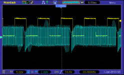
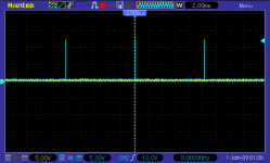
There's the scope trace with CH1 at 1000rpm simulation of G28 and CH2 showing a rock solid 33Hz output. I need to hook up a potentiometer and sweep the range from 0 - redline... next step is to verify the min rpm when ECU activates the fuel pump - I think I already found where that is defined but I have to check it before declaring victory.

1789732764799.png

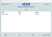
And VCDS reporting engine speed in the right place ...

1789732813287.png
 
   #12  

nugentp

Verified VCDS User
Verified
Joined
Jan 3, 2019
Messages
1,033
Reaction score
582
Location
UK
VCDS Serial number
C?ID=6386
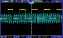
Some more fun today then... I wasn't happy with the shape of my simulated G28 signal with the way the DC bias was drifting around the gaps - some effect of the magnetics, so I changed the RC network feeding the primary side of the transformer and yielded this much prettier signal - running here with 500us tooth width to yield exactly 960rpm which correctly is reflected by 32Hz square wave for RPM signal out of pin 37.

1789751074686.png

That new RC network of 1.2kohm and ~20uF in series with the cheap little audio transformer proved its worth working from 0 to 8krpm essentially. It took some experimentation to get those values where the signal stayed good and clean all the way to the floor. With bad RC choices I was having the ECU throw up DTCs for G28 implausible signal. I just used UTP for a very short run on the bench... when time allows I might tidy it all up with nicely connectorized loom and STP cable.

I had to modify the G28 simulation code to work with delays in milliseconds when I got into the lower registers (Arduino has a bug where the delay milliseconds function goes haywire beyond 16ms) as I wanted to find the point where the fuel pump relay (FPRy) gets de-activated and to see how/where this is controlled in the ME7 calibration.

By slowing the G28 signal down gradually, I found it reliably turned off an LED I had hooked into the FPRy pin at 20rpm and that aligns to a flywheel tooth period of 50ms. 20rpm is 1200 G28 teeth per minute ==> 20 G28 teeth per second and the reciprocal of that yields 50ms.

There is an ME7 param called TZZMX in the FPRy section which is defined to be 50ms - I think that is maximum time between teeth before FPRy is activated. Its certainly one helluva coincidence - I need to flash a different value in there and retest on the bench to prove this one done as a little exploration. Fun for a Friday.

UPDATE - after testing with TZZMX set for 10ms in anticipation of FPRy being cut off at 100rpm, sadly that is not the case - it just so happens that fuel pump parameter relating somehow to a maximum tooth period was 50ms so it was a false positive... some other constant is controlling the 20rpm rate... maybe there is a higher order selection where it picks the lowest of multiple CW values. The mystery continues.

Further update - after checking the FR I found I had overlooked a parameter for this called NMIN - set for 25rpm when FPRy is activated. I was able to change that to 50rpm, reflash and verify on the scope. Curiously the 20rpm value I was seeing before was when engine speed was being reduced and that's what fooled me with the 50ms coincidence.
 
Last edited:
   #13  

nugentp

Verified VCDS User
Verified
Joined
Jan 3, 2019
Messages
1,033
Reaction score
582
Location
UK
VCDS Serial number
C?ID=6386
Before anyone wonders why 500us tooth width (1ms tooth period) yields 960rpm and not text book 1krpm - its the processing time in the Arduino code that skews things a small amount at the cost of great convenience. When the code runs with a value of 500us for a tooth width that's 1ms for a tooth period of 60ms for a whole revolution but the processing time is approx 2.5ms so I end up with a rotation period of 62.5ms and that means rpm = 60/0.0625 = 960rpm.

The burden of processing time skews things more at higher speeds but we aren't looking to have position 1 of 2 yield an exact speed - I just define the broad range and it kicks teeth like a champ well beyond 8krpm where its nominally working off a 50us tooth width (that should yield 10krpm before processing time is accounted for).

For sure there are more elaborate timer driven simulator sketches for this kind of thing if you want sexy code or need super accuracy but it was quick and easy to just kick bits and count time to get a viable signal for this kind of functional test on the bench.
 
   #14  

Zenerdiode

Verified VCDS User
Verified
Joined
Jun 26, 2014
Messages
1,559
Reaction score
2,316
Location
Newcastle, England
VCDS Serial number
C?ID=24330
Like everything ME7 there are other layers of hidden complexity to promote an output into the output test party. I tried to do this today for the fuel pump relay which is annoyingly not actionable from the ECU but it needs a lot more thorough investigation and knowledge to do that.

I’ve thought about that before too. The wishy-washy workaround is that when you engage the injector Output Tests, most ECUs will also engage the fuel pump.
 
   #15  

nugentp

Verified VCDS User
Verified
Joined
Jan 3, 2019
Messages
1,033
Reaction score
582
Location
UK
VCDS Serial number
C?ID=6386
Not sure you would actually want the fuel pump running while pulse testing injectors in the engine. I only use that test as a quick audible / tactile check that wiring to each injector is functioning and in the right order. It's just annoying you cannot activate the FPRy on this ECU from OBD output tests.

I know aftermarket ECUs allow you to tickle all outputs including coil packs but I can imagine it being potentially litigious in a dealership garage when someone tests for sparks after the injectors have potentially puffed a bit of fuel around.
 
   #16  

nugentp

Verified VCDS User
Verified
Joined
Jan 3, 2019
Messages
1,033
Reaction score
582
Location
UK
VCDS Serial number
C?ID=6386
I've only gone and bl@@dy done it :-) Explicit output test for fuel pump relay (J17) enabled on ME7.5 1.8T binary (BFB/BEX)

After much ado and artificial assistance doing the guided heavy lifting of disassembly and linking many dots, "we" found the diagnostic routine for the FPRy that was lurking in the ME7.5 binary as a dormant piece of code that was not getting called directly in the output tests for this calibration. Long story short, the handler reference (a single byte number) for this function was found and used to take the 1st place in the O/P test sequence and I demoted the N80/EVAP to a later position in the sequence - hijacking the bit-mask that was reserved for LDP testing along the way - unused in UK/EU market so its no loss.

This means the fuel pump can now be activated first in the sequence instead of having to click thru umpteen times.

The other curiosity - verified with OE code is that the FPRy is actually enabled for all of the tests in the sequence - it provides the switched 12V supply to fuses for the MAF, INJs & J299 relay as well as the actual fuel pump. There must be a Bosch test strategy that J17 is active for all of the tests in progress regardless whether it is needed or not. I didn't dare go looking for that - I consumed enough complexity today.

So its a fact that in OE condition that FPRy/J17 was being implicitly activated by the first test (N80/EVAP) but it is just more logical to me to present the J17 test first and to do so explicitly.

Total of 3 x byte changes (ignoring programmatic csum changes). Amazing - well to me anyway.


1789841924304.png
 
   #17  

nugentp

Verified VCDS User
Verified
Joined
Jan 3, 2019
Messages
1,033
Reaction score
582
Location
UK
VCDS Serial number
C?ID=6386
Highlight of today so far in this regard was confirming that the fuel consumption signal (KVA) remains active on this ECU at pin 81 - not shown on BFB/BEX schematic but it's there and active without any SW pokery. I was just able to verify its presence with the faked G28 signal enough to make the ECU think the engine is alive for 1-2s before a long list of implausible things get raised on the bench with fundamental things like a MAF, DBW, ETB missing. I captured the brief KVA pulse period to confirm it matches with ~100Hz stated in the ME7 FR.

Oh I also verified that pins 47 and 48 are MIL/CEL and EPC lamp outputs respectively actively switched to 0V when faults are present. I had to crush a number of DTCs in bench mode to get the lamps out (during another fake run event). Took me a while to figure that out but a nicely organised.KP file makes things so much easier once you figure out what terminology to search for (in technical German which has been a massive barrier for me until I started leaning on AI for that and their skills at C167 disassembly.

I will post more pics to add some more colour to this (if anyone else is interested in such retrofit pokery).
 
Last edited:
   #18  

nugentp

Verified VCDS User
Verified
Joined
Jan 3, 2019
Messages
1,033
Reaction score
582
Location
UK
VCDS Serial number
C?ID=6386
There is the KVA captured before the ECU cries foul about bench operations with umpteen things unplugged - how on earth am I doing 100kph at 960rpm without a throttle body or a MAF lol. That 10.2ms (ish) between pulses is what is expected... the +ve width of the KVA pulse extends in a linear fashion with fuel consumption with 100% DC == 93.6L/hr (which would be a lot of fuel). Its then up to the cluster to take that signal in addition to VSS in order to present a value in the trip computer in terms of liter/km or miles/gallon (depending on cluster coding for units of measurement).

If anyone cares, the exact timer period is handled in PP0 and derived from 5000 * 64 / CPU_clock_frequency. The C167 is clocked at 31.25MHz so we get exactly 10.24ms.

1790005701183.png
 
Last edited:
   #19  

nugentp

Verified VCDS User
Verified
Joined
Jan 3, 2019
Messages
1,033
Reaction score
582
Location
UK
VCDS Serial number
C?ID=6386
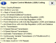
I have continued a bit more with the digital archelogy and reverse engineering. Disabling the "ABS rough road" DTC took more effort than I expected. On the 6R32 ME7.1.1 ECU there is a single codeword for that, but on the ME7.5 there is a table of eight possibilities which are determined by the variant coding table (VARTAB), aligned to the soft coding value (SCV).

18014 - Rough Road/Engine Torque Signal from ABS P1606 - 001 - Electrical Malfunction

Basically there is one algorithm for drivetrain types 0 or 2 where the codeword is relevant, while with drivetrains type 5 or 7 it is not required as a different CAN based mechanism is used to validate the road speed vs engine speed signals for plausibility.

So once all the code was unravelled it was possible to verify with different SCV values on my test rig which allows RPM rates to rise stupidly fast (like wheel spin), so when I zero out the corresponding table the DTC for P1606 does not return even with SCV = xx0xx or xx2xx. I did that WITHOUT crushing any DTC codes - just changed an input/flag to the non CAN based algorithm.

Along the way I did learn how to crush a number of DTC codes as I wanted to fool the ECU into thinking it was fault free so the undocumented MIL & EPC lamp pins (47 & 48) could be verified to be working as expected.

1790167451325.png
 
   #20  

nugentp

Verified VCDS User
Verified
Joined
Jan 3, 2019
Messages
1,033
Reaction score
582
Location
UK
VCDS Serial number
C?ID=6386
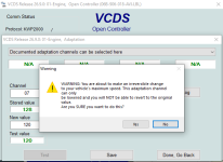
Then I ventured into a domain that I had no prior knowledge of... namely multiple layers of authorisation to various adaptation channels - of which there are ~14 available on this ECU.
All are read-only without a special login but I found some get unlocked, for write access, with a dealership (K-login) code and the whole list gets unlocked with a specialist/engineer code (S-login). The latter found a hidden feature on VCDS that I had not seen before - it clearly knows about this behind the scenes to present the pop-up.

1790167946773.png

I wont share the special codes here, but they are probably published somewhere and anyone with WinOLS, the correct .KP file and two working brain cells could find them.

The interesting part is the factory SW logic does indeed only allow you to reduce VMAX by 127kph from whatever the hard coded limit is in the binary... you cannot increase it. I could probably spend an afternoon finding and changing the logic that would allow an S-login to decrease or increase VMAX by 127kph...

The decrease trick is maybe of interest for a sneaky valet/spouse mode as the change does survive on/off or even battery on/off - you have to use another S-login session to change it back.

There are some other cool tricks in there under those hidden adaptation channels to affect not only idle speed, but warm up enrichment, ignition advance and others - I don't want to publish it here in case it crosses into 'verboten' territory with Ross Tech way of working as these are clearly specialised mechanisms to be only used by people that have more than a vague clue about what they are getting into.
 
Back
Top