Audi A6 C7 Facelift Estate rear camera retro fit

   #21  

SBJ

Verified VCDS User
Verified
Joined
Jul 24, 2018
Messages
36
Reaction score
4
Location
UK
VCDS Serial number
C?ID=105394
Just to add to this, my A6 C7 is FL MY2018 has had a reversing camera installed with integrated module and have the same CAN fault message:

Code:
Address 19: CAN Gateway (J533)       Labels:* None
   Part No SW: 4G8 907 468 K    HW: 4G8 907 468 
   Component: J533--Gateway H15 0110  
   Revision: --------    Serial number: 00000002944682
   Coding: C0CD074418
   Shop #: WSC 02391 785 00200
   ASAM Dataset: EV_GatewPkoUDS 002011
   ROD: EV_GatewPkoUDS_002_AU57.rod
   VCID: 408450DDDB25F88442-8014

1 Fault Found:
5807 - Rear View Camera System Control Module 
          U104C 00 [008] - No communication
          Intermittent - Confirmed - Tested Since Memory Clear

Yes the camera works however knowing it isn't quite as Audi intended is pushing me to understand & resolve this fault, OCD kicking in!

Code:
Address 6C: Back-up Cam. (J772)       Labels:| 4S0-980-556.clb
   Part No SW: 4S0 980 556 A    HW: 4M0 980 556 A
   Component: RVC Compact   H15 0201  
   Coding: 0275000102002003000040
   Shop #: WSC 79104 790 00000
   ASAM Dataset: EV_CamSysRVRVCPANAAU57X 002003
   ROD: EV_CamSysRVRVCPANAAU57X_002.rod
   VCID: 39723D39B8FFA94C05-806C
No fault code found.

[5f]
ENG12229-ENG117712-Car_Function_List_BAP_Gen2-VPS_0x0B = activated
ENG122229-ENG117713-Car_Function_List_BAP_Gen2-VPS_0x0B_msg_bus = Terminal 15


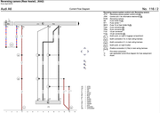
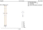
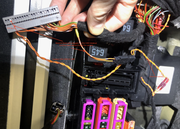
erWIN diagram 116/2 shows power from [SB ST1] which is a switched fuse and diagram 116/3 shows CAN Extended high/low into [J533] under the rear seat. However my camera has been connected into the rear boot panel CAN breakout which I don't think is correct based on what erWIN wiring diagram 116/3 indicates.

It is obviously communicating on CAN but perhaps not CAN Extended?
1. Would rewiring into J553 CAN Extended (under rear seat) resolve the fault as the system would send the correct message?
2. and would I need to change the above msg_bus to CAN Extended?

Any guidance would be very much appreciated.

Thanks in advance!
 
Last edited by a moderator:
   #22  

langers2k

Verified VCDS User
Verified
Joined
Oct 20, 2014
Messages
467
Reaction score
441
Location
UK
VCDS Serial number
C?ID=224085
@SBJ - Given the camera is working correctly, I think it's probably on suitable CAN-bus? Feel free to try moving the CAN connection or changing VPS_0x0B_msg_bus to see if it helps but I don't think it will.

Much like the OP, The intermittent comms is probably due to it having a switched live rather than a permanent live. For starters, I'd try giving it a permanent live to see if that works or if you get the same issues as the OP with battery drain and confused clicks from the handbrake module. As your car is newer, this might be enough to fix it.

You could also ask one of the many members with a similar car if they can confirm the factory coding (and 09 adaptions) for their camera, example scans with the same gateway and similar cameras:
- https://forums.ross-tech.com/index.php?threads/25837/
- https://forums.ross-tech.com/index.php?threads/18969/
- https://forums.ross-tech.com/index.php?threads/20948/#post-183649
- https://forums.ross-tech.com/index.php?threads/13109/#post-119120

Saying that, it looks like the factory camera has a slightly different hardware/software to the one you've fitted - not sure if that'll cause any issues.
 
   #23  

szymek

Verified VCDS User
Verified
Joined
Oct 16, 2020
Messages
87
Reaction score
21
Location
UK
VCDS Serial number
C?ID=414515
Hi
i tried this morning with extended can and changed adaptations in 5f to all possible and with no changes...
@SBJ don't try with permanent live...
I think the problem is hardware....I need to try to reflash when I get the right one from someone
in this post Au07 - https://forums.ross-tech.com/index.php?threads/20948/#post-183649 have same HW what i have and he has no no communication fault
 
Last edited:
   #24  

langers2k

Verified VCDS User
Verified
Joined
Oct 20, 2014
Messages
467
Reaction score
441
Location
UK
VCDS Serial number
C?ID=224085
Why shouldn't SBJ try a permanent live?

Just because the solution isn't right for you, doesn't mean it's not right from someone with a newer, differently configured car. Especially with a CAN-gateway which appears to supports this style of camera rather then the older J772 style your car seems to expect.

Obviously if they do try it, they should check for battery drain and handbrake clicking. Still seems a no brainer for moving/adding a single wire to test it :confused:
 
   #25  

szymek

Verified VCDS User
Verified
Joined
Oct 16, 2020
Messages
87
Reaction score
21
Location
UK
VCDS Serial number
C?ID=414515
Why shouldn't SBJ try a permanent live?

Just because the solution isn't right for you, doesn't mean it's not right from someone with a newer, differently configured car. Especially with a CAN-gateway which appears to supports this style of camera rather then the older J772 style your car seems to expect.

Obviously if they do try it, they should check for battery drain and handbrake clicking. Still seems a no brainer for moving/adding a single wire to test it :confused:


check that after 2015 the camera requires switched live, no matter if 2015 or 2018
 
   #26  

SBJ

Verified VCDS User
Verified
Joined
Jul 24, 2018
Messages
36
Reaction score
4
Location
UK
VCDS Serial number
C?ID=105394
Why shouldn't SBJ try a permanent live?

Just because the solution isn't right for you, doesn't mean it's not right from someone with a newer, differently configured car. Especially with a CAN-gateway which appears to supports this style of camera rather then the older J772 style your car seems to expect.

Obviously if they do try it, they should check for battery drain and handbrake clicking. Still seems a no brainer for moving/adding a single wire to test it :confused:

Thanks for the replies. erWIN shows the camera wired into a switched not a permanent supply. It was more the CAN wiring and whether Extended CAN with the correct coding combination was the correct approach?
 
   #27  

SBJ

Verified VCDS User
Verified
Joined
Jul 24, 2018
Messages
36
Reaction score
4
Location
UK
VCDS Serial number
C?ID=105394
Connecting to permanent live I'm sure will resolve the CAN error as the camera module will be present when the car wakes up but may very well introduce a battery drain which I'd rather not have.

erWIN wiring shows the connections to switched live and Extended CAN for MY2018. With VCDS is there a way of monitoring the Extended CAN to see if it is sending the relevant message for the camera? I'd like to know before I pull the rear seat out and potentially have to rewire into the extended CAN. Similarly, is the camera module coded correctly and how would I know?

Thanks
 
   #28  

SBJ

Verified VCDS User
Verified
Joined
Jul 24, 2018
Messages
36
Reaction score
4
Location
UK
VCDS Serial number
C?ID=105394
@SBJ - Given the camera is working correctly, I think it's probably on suitable CAN-bus? Feel free to try moving the CAN connection or changing VPS_0x0B_msg_bus to see if it helps but I don't think it will.

Much like the OP, The intermittent comms is probably due to it having a switched live rather than a permanent live. For starters, I'd try giving it a permanent live to see if that works or if you get the same issues as the OP with battery drain and confused clicks from the handbrake module. As your car is newer, this might be enough to fix it.

You could also ask one of the many members with a similar car if they can confirm the factory coding (and 09 adaptions) for their camera, example scans with the same gateway and similar cameras:
- https://forums.ross-tech.com/index.php?threads/25837/
- https://forums.ross-tech.com/index.php?threads/18969/
- https://forums.ross-tech.com/index.php?threads/20948/#post-183649
- https://forums.ross-tech.com/index.php?threads/13109/#post-119120

Saying that, it looks like the factory camera has a slightly different hardware/software to the one you've fitted - not sure if that'll cause any issues.
Thanks - I've cross referenced the camera modules from the above 5 examples and they all have:

Address 6C: Back-up Cam. (J772) Labels:| 4S0-980-556.clb
Part No SW: 4S0 980 556 HW: 4M0 980 556
Component: RVC Compact H08 0140
Coding: 0275000102002003000040

My camera:
Address 6C: Back-up Cam. (J772) Labels:| 4S0-980-556.clb
Part No SW: 4S0 980 556 A HW: 4M0 980 556 A
Component: RVC Compact H15 0201
Coding: 0275000102002003000040


So the coding looks the same as does the SW and HW except for the 'A' suffix. And the component. Any significance? Bearing in mind erWIN states it should be connected to Extended CAN for MY2018. So trying to eliminate wiring, coding, hardware!
 
   #29  

langers2k

Verified VCDS User
Verified
Joined
Oct 20, 2014
Messages
467
Reaction score
441
Location
UK
VCDS Serial number
C?ID=224085
Not sure exactly what the "Part No SW", "HW" and the "Hx 0xxx" versions mean in terms of compatibly for these cameras.

In most cases I've found, "Part No SW: 4S0 980 556 A" seems to be fitted to an R8 although it has very different "HW: 95B 980 551 L".

Might be worth asking @Rizzio as it looks like they have a similar(?) camera (based on Part No SW) fitted to an 2015(?) A6 C7 but with a slightly older gateway in this thread: https://forums.ross-tech.com/index.php?threads/19830/
Code:
Address 19: CAN Gateway (J533)       Labels:* None
   Part No SW: 4G8 907 468     HW: 4G8 907 468 
   Component: J533--Gateway H13 0075  

Address 6C: Back-up Cam. (J772)       Labels:| 4S0-980-556.clb
   Part No SW: 4S0 980 556 A    HW: 5Q0 980 556 B
   Component: RVC Compact   H12 0201

Given the "HW: 5Q0 980 556 B" part, I expect their camera is also a retrofit...? They've been online in the last few weeks so hopefully they'll get an email notification I've mentioned them and give some insight.

Just as a side note, the RVC I retrofitted to my MQB Octavia with a permanent live shares "HW: 4M0 980 556 A" with yours:
Code:
Address 6C: Back-up Cam. (J772)       Labels:| 5Q0-980-556.clb
   Part No SW: 5Q0 980 556 B    HW: 4M0 980 556 A
   Component: RVC Compact   H12 0231

Seems like the HW might not be that important and they can take a few different SW versions depending what car they are destined for...
 
  • Like
Reactions: SBJ
   #30  

SBJ

Verified VCDS User
Verified
Joined
Jul 24, 2018
Messages
36
Reaction score
4
Location
UK
VCDS Serial number
C?ID=105394
Assuming the HW and camera SW coding are good, there appears to be only 2x real options (please correct me!):

1. Existing Adaptations:
[5f]
ENG12229-ENG117712-Car_Function_List_BAP_Gen2-VPS_0x0B = activated
ENG122229-ENG117713-Car_Function_List_BAP_Gen2-VPS_0x0B_msg_bus = Terminal 15
<-- I could try Extended CAN (and all other options). @szymek has tried this with no success but my MY is later etc.

2. CAN Wiring:
erWIN shows CAN High & Low should be connected to the J533 under the rear seat pins 18 & 2. My camera is currently connected into the CAN in the boot and before physically changing anything want to know some more...
With VCDS is there a way of monitoring the Extended CAN (& CAN) to see if the car is sending the relevant messages (a bit like WireShark!), how would I set this up? And could I send a power on/off message to the camera with VCDS to see if it responds correctly? @Uwe @Dana is this possible?

As I said earlier, the camera works fine its just the fault being reported which I would like to resolve.

Thanks in advance!
 
   #31  

szymek

Verified VCDS User
Verified
Joined
Oct 16, 2020
Messages
87
Reaction score
21
Location
UK
VCDS Serial number
C?ID=414515
Assuming the HW and camera SW coding are good, there appears to be only 2x real options (please correct me!):

1. Existing Adaptations:
[5f]
ENG12229-ENG117712-Car_Function_List_BAP_Gen2-VPS_0x0B = activated
ENG122229-ENG117713-Car_Function_List_BAP_Gen2-VPS_0x0B_msg_bus = Terminal 15
<-- I could try Extended CAN (and all other options). @szymek has tried this with no success but my MY is later etc.

2. CAN Wiring:
erWIN shows CAN High & Low should be connected to the J533 under the rear seat pins 18 & 2. My camera is currently connected into the CAN in the boot and before physically changing anything want to know some more...
With VCDS is there a way of monitoring the Extended CAN (& CAN) to see if the car is sending the relevant messages (a bit like WireShark!), how would I set this up? And could I send a power on/off message to the camera with VCDS to see if it responds correctly? @Uwe @Dana is this possible?

As I said earlier, the camera works fine its just the fault being reported which I would like to resolve.

Thanks in advance!
not only you want to solve this problem. I asked a few colleagues if I find something, I would share the information ...
 
  • Like
Reactions: SBJ
   #32  

langers2k

Verified VCDS User
Verified
Joined
Oct 20, 2014
Messages
467
Reaction score
441
Location
UK
VCDS Serial number
C?ID=224085
If I were you, I'd start by checking the wiring diagram and figuring out which CAN-bus the camera is and should be connected to. It shouldn't matter where on a CAN-bus a module is connected, only that it's on the correct one as per the factory diagram. I'd then probably change VPS_0x0B_msg_bus to match the one used.

Not convinced that will help with the intermittent comm's though. That still feels like the CAN gateway is expecting a response from the camera when it's been powered down due to the switched live...

Out of curiosity, are you getting the WD directly from erwin or finding them online?
 
   #33  

SBJ

Verified VCDS User
Verified
Joined
Jul 24, 2018
Messages
36
Reaction score
4
Location
UK
VCDS Serial number
C?ID=105394
If I were you, I'd start by checking the wiring diagram and figuring out which CAN-bus the camera is and should be connected to. It shouldn't matter where on a CAN-bus a module is connected, only that it's on the correct one as per the factory diagram. I'd then probably change VPS_0x0B_msg_bus to match the one used.

Not convinced that will help with the intermittent comm's though. That still feels like the CAN gateway is expecting a response from the camera when it's been powered down due to the switched live...

Out of curiosity, are you getting the WD directly from erwin or finding them online?

WD directly from erWIN. I would post on here but can't paste images for some reason.
erWIN diagrams 116/2 & 116/3 show power to SB ST1 (switched) and CAN Extended High 18 and Low 2 into the J533 under rear seat.

Would the camera module get a wake up call via the Extended CAN? And if the power is from a switched fuse, how does it power up if the ignition is off or is the CAN message to/from the camera enough? I don't understand how this part works (can you tell?!).
 
   #34  

langers2k

Verified VCDS User
Verified
Joined
Oct 20, 2014
Messages
467
Reaction score
441
Location
UK
VCDS Serial number
C?ID=224085
Rosstech won't host images so you need to upload them to a 3rd party site such as https://postimages.org/

Based on your WD, you know the camera should be connected to extended CAN. The next thing to check is which CAN-bus the "CAN in the boot" is actually connected to. Hopefully it's also extended CAN to make your life easier :)

In my car, a CAN-bus message tells the camera to turn on/off and if the ignition is off (to reduce power consumption).

It seems like your car expects something different if the camera is on a switched live. It obviously can't communicate if the ignition is off as it has no power, the question is why is something expecting it to communicate and causing the fault code. I would still expect a CAN-bus message to actually turn the camera on/off when reverse is selected etc.

If your battery is in good condition and you can monitor the standby current, I'd still be tempted to try a permanent live by just using a fused jump wire. Assuming you fitted a fuse for the camera it should be a 30s job to make a wire and temporarily make it permanent live. If nothing else, it's just to check you have the same battery drain issue that the OP does despite having a newer car.

Did you try PM'ing any of the members with factory fitted cameras or Rizzio? Feels like an adaption map of a 'good' car would be super helpful at this point, even more if they can confirm their camera power source!
 
   #35  

SBJ

Verified VCDS User
Verified
Joined
Jul 24, 2018
Messages
36
Reaction score
4
Location
UK
VCDS Serial number
C?ID=105394
Silly question time...
How do I monitor the standby current with VCDS? Would love to know if anything is draining things. The car battery had a few sluggish starts in the past so have been using a CTEK battery charger to keep it healthy. The camera power was wired into the rear of ST1 fuse carrier so its not a 30 second job to move to a permanent live, plus the diagrams:


Good call, I'll ask for an adaptation map also.

Thanks for your help.
 
   #36  

Bruce

Active Member
Staff member
Ross-Tech Employee
Joined
Jan 30, 2014
Messages
3,184
Reaction score
5,165
Location
Near Philadelphia, PA, USA
VCDS Serial number
--------
How do I monitor the standby current with VCDS? Would love to know if anything is draining things. The car battery had a few sluggish starts in the past so have been using a CTEK battery charger to keep it healthy.

I am not aware of a sensor in the main battery path that VCDS could query for the stanby current. To measure standby current, one should use a multimeter or a clamp on ammeter. If you measure the current right at the battery, you will know the current draw. Clamp the ammeter to either the ground (-) or the hot lead (+). The value should be same.. if Kirchoff's current law still holds true. (I struggle today knowing what remains true!)
 
   #37  

langers2k

Verified VCDS User
Verified
Joined
Oct 20, 2014
Messages
467
Reaction score
441
Location
UK
VCDS Serial number
C?ID=224085
Can you find out what the grey connector is, then find it on the WD to see which CAN-bus is at pins you've used. If it's extended CAN, then that should be fine.
 
  • Like
Reactions: SBJ
   #38  

Uwe

Benevolent Dictator
Administrator
Joined
Jan 29, 2014
Messages
49,293
Reaction score
33,820
Location
USA
VCDS Serial number
HC100001
I am not aware of a sensor in the main battery path that VCDS could query for the stanby current.
On cars that have a Battery Monitoring Control Module such as the one one that's a sub-system of the gateway shown in the scan on the first post of this thread, there's definitely a current sensor.

Code:
Address 19: CAN Gateway (J533)       Labels:* None
   Part No SW: 4G0 907 468 AE    HW: 4G0 907 468 AC
   Component: J533--Gateway H13 0075
   Revision: --------    Serial number: 00000001715362
   Coding: C0CD074418
   Shop #: WSC 02391 785 00200
   ASAM Dataset: EV_GatewPkoUDS 001024
   ROD: EV_GatewPkoUDS_001_AU57.rod
   VCID: 73B3DB963B315B937E1-8026

   Battery Monitoring Control Module:
   Subsystem 1 - Part No SW: 8T0 915 181     HW: 8T0 915 181
   Component: J367-BDMHella  H03 8041
   Serial number: 1841145603

However, I'm not sure it can be monitored with VCDS in real-time with the ignition off, and if it can, it's possible that attempting to do so will keep things awake that should be asleep.

However, one can certainly look at the Battery History data, and it will show whether there is excessive draw when the car should be powered down.

-Uwe-
 
  • Like
Reactions: SBJ
   #39  

SBJ

Verified VCDS User
Verified
Joined
Jul 24, 2018
Messages
36
Reaction score
4
Location
UK
VCDS Serial number
C?ID=105394
Just been on erWIN again:

T46b (connector in the boot for the CAN diagnostic port) connector pins 21H & 21L is where my camera is spliced into which turns out to connect to the Dashpanel CAN. This is not the extended CAN.


T46 connector pins 8H & L are the convenience CAN.


Since erWIN states my MY2018 A6 camera module should be connected to the Extended CAN, this is categorical that its not wired as per Audi spec. However, could the wake up signal also be sent via the dash panel CAN? Similarly could the wakeup signal be sent via the convenience CAN if ENG122229-ENG117713-Car_Function_List_BAP_Gen2-VPS_0x0B_msg_bus = is set accordingly?

And do either CANs (convenience or extended) msg_bus setting work considering Audi (erWIN) state the power is wired into a T15 switched power supply?

Power showing it is fed from a T15 fuse

Thanks.
 
Last edited:
   #40  

SBJ

Verified VCDS User
Verified
Joined
Jul 24, 2018
Messages
36
Reaction score
4
Location
UK
VCDS Serial number
C?ID=105394
Before embarking on rewiring things, will moving the CAN from its current wiring (dash panel CAN) to the erWIN defined Extended CAN make any difference to the fault? Given the camera module is on a T15 switched live, I don't understand how this can resolve the issue. Are there certain switched T15 fuse locations that also turn on in unison with a CAN message?
Reminder:
5807 - Rear View Camera System Control Module
U104C 00 [008] - No communication
Intermittent - Confirmed - Tested Since Memory Clear


If CAN signals to a module to turn on, surely it has to be on a T30 power feed?

Just wondering how much effort to put into this if the logic is flawed from the start and potentially the erWIN wiring diagrams have a potential inaccuracy. erWIN states to use the Extended CAN and T15 power.

Thanks for all your inputs in the previous messages.
 
Back
Top