
- Joined
- Jan 29, 2014
- Messages
- 21,923
- Reaction score
- 9,308
- Location
- Montgomery, NY, USA
- VCDS Serial number
- C?ID=57337
Alternator and charging system basics by NostraJackASS!
http://forums.ross-tech.com/showthread.php?3147-What-is-Jack-talking-about-0x01-08-000
Load Management for integration of J519 Convenience "0x09" and integration to use the Alternator and Gateway "0x19" or Engine computer "ECU/ECM 0x01"
Dynamic or Dynamo field observations......... ( DF )
Load Management Activation Sequence: The 0x01 receives the DF (Dynamo Field) and RPM signals.
The DF signal originates in the alternator and is used to determine alternator charging capacity.
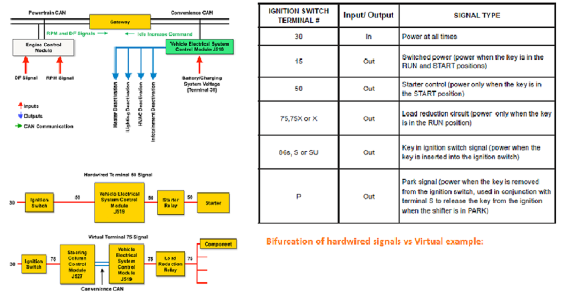
The ECM broadcasts the DF and RPM signals on the powertrain CAN. Gateway 0x19, then rebroadcasts this message on the convenience CAN. J519 0x09 receives the DF and RPM signals from the convenience CAN. J519 also receives the battery/charging system voltage via terminal 30.
Terminal 30 means B+ voltage at all times!
Load Management Activation Sequence:
The ECM receives the DF (Dynamo Field) and RPM signals.
The DF signal originates in the alternator and isused to determine alternator charging capacity.
The ECM broadcasts the DF and RPM signals on the powertrain CAN. Gateway then rebroadcasts this message on the convenience CAN. J519 receives the DF and RPM signals from the convenience CAN. J519 also receives the battery/charging system voltage via terminal 30.
J519 evaluates the DF, RPM and voltage signals. If the voltage drops below a predetermined threshold, J519broadcasts an idle RPM increase command on the convenience CAN. Gateway then rebroadcasts thismessage on the powertrain CAN.
The ECM receives and complies with the idle RPM increase request.
If the increased idle RPM does not resolve the low voltage condition or if the low voltage condition occurs aboveidle, J519 begins to deactivate high current comfort components in a pre-programmed sequence. In somevehicles, a load management notification appears in the instrument cluster and DTCs are logged in faultmemory.
When the low voltage condition is resolved and voltage increases above the threshold, component deactivationis canceled. Component deactivation also occurs with the key on engine off using a lower voltage threshold.
Bifurcation of Hardwired signals vs Virtual example:
https://s33.postimg.cc/wa0op9h67/j519_and_terminals.png
https://s33.postimg.cc/pwblm0ca5/j519_and_terminals.png?dl=1
https://s33.postimg.cc/hoxk0mlsf/cropped.png Attempt at CROP 1
Download the image and follow along by blowing it up........
The terminal 50 signal shown above is an example of a hardwired signal. Hardwired signals are also called discrete signals too & are carried on a dedicated single function wire.
In this example, a hardwire carries the 50 signal between all of the components in the circuit.
The advantage of a hardwired signal is that it can be easily verified.
In this case the terminal 50 signal is a positive voltage that can be measured with a with a DVOM or with VCDS Advanced Block values.
The disadvantage is that every hardwired signal requires a dedicated wire, increasing the complexity of the wiring harness.
The terminal 75 (X) signal shown above is an example of a virtual signal.
While it may be carried between some components as a hardwired signal, it is carried between others as a virtual signal.
In this example:
The terminal 75 signal originates in the ignition switch and is sent to J527 via a hardwire.
J527 receives the 75 signal and converts it to a CAN message (virtual 75 signal) which is broadcast to J519 on the convenience CAN.
J519 receives the CAN message and internally switches power to a hardwired 75 circuit.
The 75 signal is received by the load reduction relay.
The load reduction relay closes and sends power to various components.
When the ignition switch is in the start position, the ignition switch interrupts the 75 signal to J527.
J527 broadcasts a CAN message to J519 instructing it to switch off the 75 signal to the load reduction relay.
When the key is returned to the RUN position, the process repeats.
While the signal in the hardwired portions of the circuit can be verified with a DVOM, the virtual portion can only be
verified with VCDS Advanced blocks.
The advantage of virtual signals is that many different signals can be carried on the CAN wires, eliminating the individual hardwire circuits.
This reduces the complexity of the warning harness.
The examples shown above are used to explain the concept of virtual signals.
The actual connection for virtual signals varies per vehicle, although the concept remains the same. For example, in some Jolkswagens, terminals 15 and 50 are hardwired, while terminals 75, S and P are virtual signals.
http://forums.ross-tech.com/showthread.php?3147-What-is-Jack-talking-about-0x01-08-000
Load Management for integration of J519 Convenience "0x09" and integration to use the Alternator and Gateway "0x19" or Engine computer "ECU/ECM 0x01"
Dynamic or Dynamo field observations......... ( DF )
Load Management Activation Sequence: The 0x01 receives the DF (Dynamo Field) and RPM signals.
The DF signal originates in the alternator and is used to determine alternator charging capacity.
The ECM broadcasts the DF and RPM signals on the powertrain CAN. Gateway 0x19, then rebroadcasts this message on the convenience CAN. J519 0x09 receives the DF and RPM signals from the convenience CAN. J519 also receives the battery/charging system voltage via terminal 30.
Terminal 30 means B+ voltage at all times!
Load Management Activation Sequence:
The ECM receives the DF (Dynamo Field) and RPM signals.
The DF signal originates in the alternator and isused to determine alternator charging capacity.
The ECM broadcasts the DF and RPM signals on the powertrain CAN. Gateway then rebroadcasts this message on the convenience CAN. J519 receives the DF and RPM signals from the convenience CAN. J519 also receives the battery/charging system voltage via terminal 30.
J519 evaluates the DF, RPM and voltage signals. If the voltage drops below a predetermined threshold, J519broadcasts an idle RPM increase command on the convenience CAN. Gateway then rebroadcasts thismessage on the powertrain CAN.
The ECM receives and complies with the idle RPM increase request.
If the increased idle RPM does not resolve the low voltage condition or if the low voltage condition occurs aboveidle, J519 begins to deactivate high current comfort components in a pre-programmed sequence. In somevehicles, a load management notification appears in the instrument cluster and DTCs are logged in faultmemory.
When the low voltage condition is resolved and voltage increases above the threshold, component deactivationis canceled. Component deactivation also occurs with the key on engine off using a lower voltage threshold.
Bifurcation of Hardwired signals vs Virtual example:
https://s33.postimg.cc/wa0op9h67/j519_and_terminals.png
https://s33.postimg.cc/pwblm0ca5/j519_and_terminals.png?dl=1
https://s33.postimg.cc/hoxk0mlsf/cropped.png Attempt at CROP 1
Download the image and follow along by blowing it up........
The terminal 50 signal shown above is an example of a hardwired signal. Hardwired signals are also called discrete signals too & are carried on a dedicated single function wire.
In this example, a hardwire carries the 50 signal between all of the components in the circuit.
The advantage of a hardwired signal is that it can be easily verified.
In this case the terminal 50 signal is a positive voltage that can be measured with a with a DVOM or with VCDS Advanced Block values.
The disadvantage is that every hardwired signal requires a dedicated wire, increasing the complexity of the wiring harness.
The terminal 75 (X) signal shown above is an example of a virtual signal.
While it may be carried between some components as a hardwired signal, it is carried between others as a virtual signal.
In this example:
The terminal 75 signal originates in the ignition switch and is sent to J527 via a hardwire.
J527 receives the 75 signal and converts it to a CAN message (virtual 75 signal) which is broadcast to J519 on the convenience CAN.
J519 receives the CAN message and internally switches power to a hardwired 75 circuit.
The 75 signal is received by the load reduction relay.
The load reduction relay closes and sends power to various components.
When the ignition switch is in the start position, the ignition switch interrupts the 75 signal to J527.
J527 broadcasts a CAN message to J519 instructing it to switch off the 75 signal to the load reduction relay.
When the key is returned to the RUN position, the process repeats.
While the signal in the hardwired portions of the circuit can be verified with a DVOM, the virtual portion can only be
verified with VCDS Advanced blocks.
The advantage of virtual signals is that many different signals can be carried on the CAN wires, eliminating the individual hardwire circuits.
This reduces the complexity of the warning harness.
The examples shown above are used to explain the concept of virtual signals.
The actual connection for virtual signals varies per vehicle, although the concept remains the same. For example, in some Jolkswagens, terminals 15 and 50 are hardwired, while terminals 75, S and P are virtual signals.
Last edited:
")
